
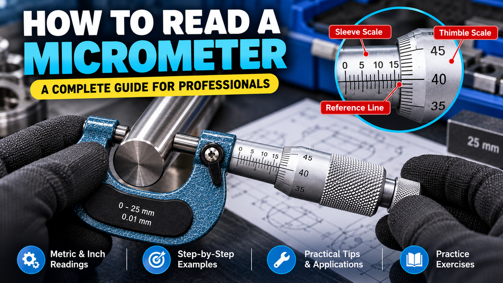
Imagine measuring a crankshaft journal during an engine inspection. You place an outside micrometer around the component, turn the thimble, and examine the graduations. The instrument is ready, but which numbers should you add together?
This is a common challenge when learning how to read a micrometer for the first time. Understanding micrometer reading is an important skill for automotive technicians, machinists, engineering students, and quality-control inspectors.
A micrometer can detect small differences in component dimensions, but obtaining a reliable measurement requires both correct scale interpretation and appropriate measuring technique.
This guide explains metric and inch micrometer readings, worked calculations, vernier scales, measurement technique, zero error, common mistakes, and professional workshop applications.
What Is a Micrometer and Why Is It Used?
A micrometer is a precision measuring instrument designed to measure dimensions such as thickness, outside diameter, inside diameter, or depth, depending on the type of instrument.
The familiar outside micrometer has a C-shaped frame, a fixed anvil, and a movable spindle. It uses a precision screw mechanism to control the distance between the measuring faces.
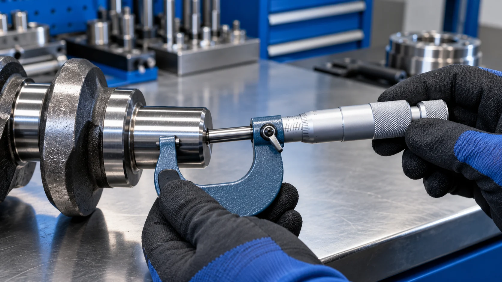
How Does a Micrometer Work?
When the thimble rotates, the precision screw advances or retracts the spindle. This changes the distance between the spindle and the fixed anvil.
Graduations on the sleeve and thimble show the position of the spindle, allowing the operator to determine the measured dimension.
Metric Micrometer
A common mechanical metric micrometer has a scale increment of 0.01 mm.
Inch Micrometer
A conventional mechanical inch micrometer commonly has 0.001-inch graduations.
Where Are Micrometers Used?
- Measuring crankshaft journal diameters.
- Inspecting automotive brake rotor thickness.
- Checking machined shafts and components.
- Measuring precision spacers and washers.
- Inspecting manufacturing tolerances.
- Quality-control measurements.
Parts of a Micrometer and Their Functions
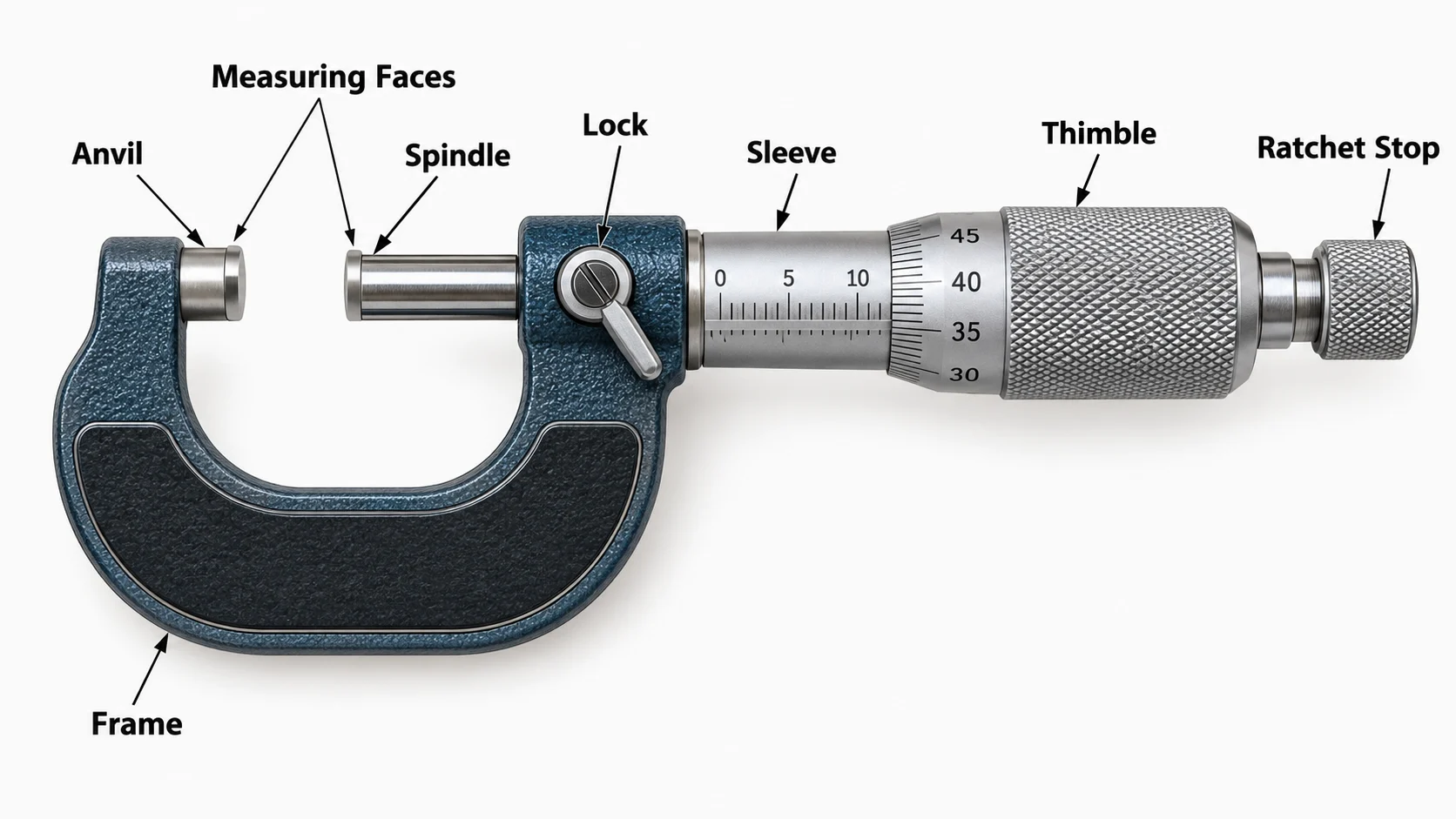
Before learning micrometer reading, identify the main components. Knowing what each part does will help you understand how the scales relate to spindle movement.
| Part | Function |
|---|---|
| Frame | Supports the measuring assembly. |
| Anvil | Provides the fixed measuring face. |
| Spindle | Moves toward or away from the anvil. |
| Sleeve | Displays the main measurement scale. |
| Thimble | Rotates the spindle and provides fine graduations. |
| Ratchet Stop | Helps maintain consistent measuring force. |
| Spindle Lock | Restricts spindle movement when engaged. |
| Measuring Faces | Contact the workpiece. |
Why Is the Ratchet Stop Important?
Excessive measuring force may deform a delicate component or affect the reading. A ratchet stop or friction device helps the user apply a more consistent force.
Always follow the manufacturer’s instructions for the number of ratchet operations or the appropriate measuring technique.
Different Types of Micrometers
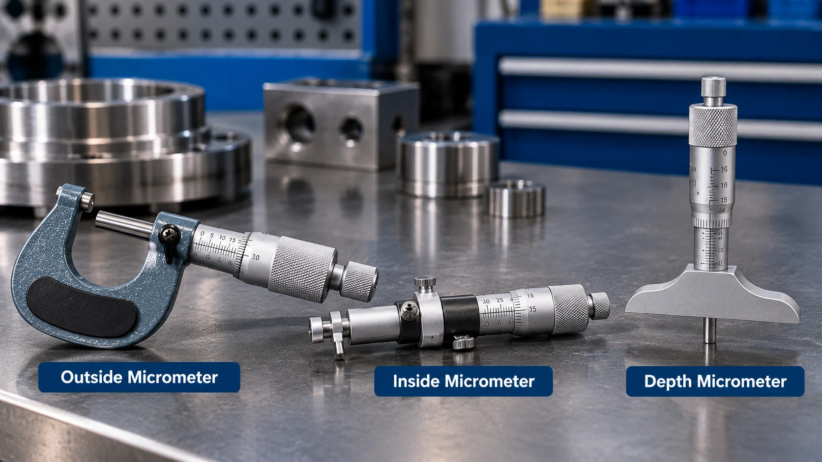
Micrometers are available in different designs because component shapes and measurement tasks vary.
| Micrometer Type | Purpose | Example |
|---|---|---|
| Outside Micrometer | External dimensions | Shaft diameter |
| Inside Micrometer | Internal dimensions | Bore measurement |
| Depth Micrometer | Depth measurements | Recess depth |
| Blade Micrometer | Narrow accessible features | Groove measurement |
| Digital Micrometer | Electronic numerical readout | Production inspection |
Which Micrometer Should Beginners Learn First?
A mechanical outside micrometer is a practical starting point. It introduces the basic sleeve and thimble reading principles used in many precision measurements.
More specialized instruments may have different measuring faces, reference procedures, and scales.
Understanding the Micrometer Sleeve and Thimble Scales
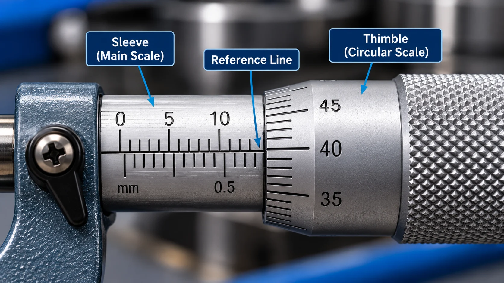
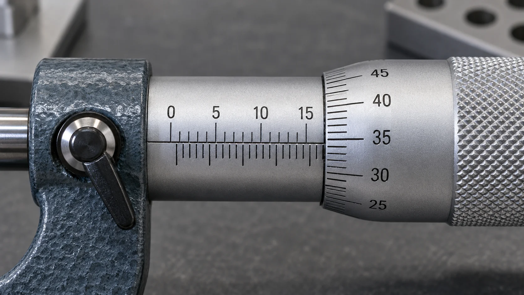
The sleeve and thimble are the two most important scales on a conventional mechanical micrometer.
The sleeve shows the main reading, while the thimble gives the smaller additional increment.
What Is the Sleeve Scale?
On a conventional metric micrometer, the sleeve shows whole-millimeter marks and half-millimeter graduations.
A conventional inch micrometer commonly uses sleeve graduations of 0.025 inch.
What Is the Thimble Scale?
The thimble carries finer graduations. The graduation aligned with the sleeve reference line provides the fine portion of the measurement.
| Scale | Common Metric | Common Inch |
|---|---|---|
| Sleeve | Whole and half millimeters | 0.025-inch increments |
| Thimble | 0.01 mm increments | 0.001-inch increments |
| Vernier, if equipped | Often 0.001 mm | Often 0.0001 inch |
How to Read a Metric Micrometer Step by Step
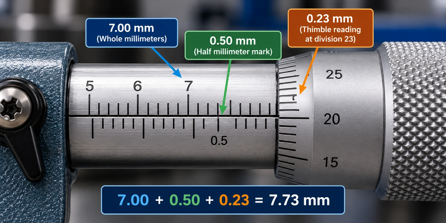
A common conventional metric micrometer has a 0.50 mm spindle pitch and 50 thimble divisions. Each thimble graduation therefore represents 0.01 mm.
Read the Whole Millimeters
Find the last fully visible whole-millimeter graduation on the sleeve. In this example, it is 7.00 mm.
Check the Half-Millimeter Mark
If the half-millimeter graduation beyond the last whole millimeter is visible, add 0.50 mm.
Read the Thimble Graduation
Identify the thimble graduation aligned with the reference line. Division 23 contributes 0.23 mm.
Add the Values
Combine all visible sleeve increments and the aligned thimble value.
This is the indicated reading of a conventional metric micrometer. Measurement accuracy must still be considered separately.
Metric Micrometer Reading Examples
Practicing different scale combinations is one of the most effective ways to improve micrometer reading skills.
Worked Metric Reading Examples
| Example | Whole mm | Half mm | Thimble | Result |
|---|---|---|---|---|
| 1 | 4.00 | 0.00 | 0.16 | 4.16 mm |
| 2 | 8.00 | 0.50 | 0.27 | 8.77 mm |
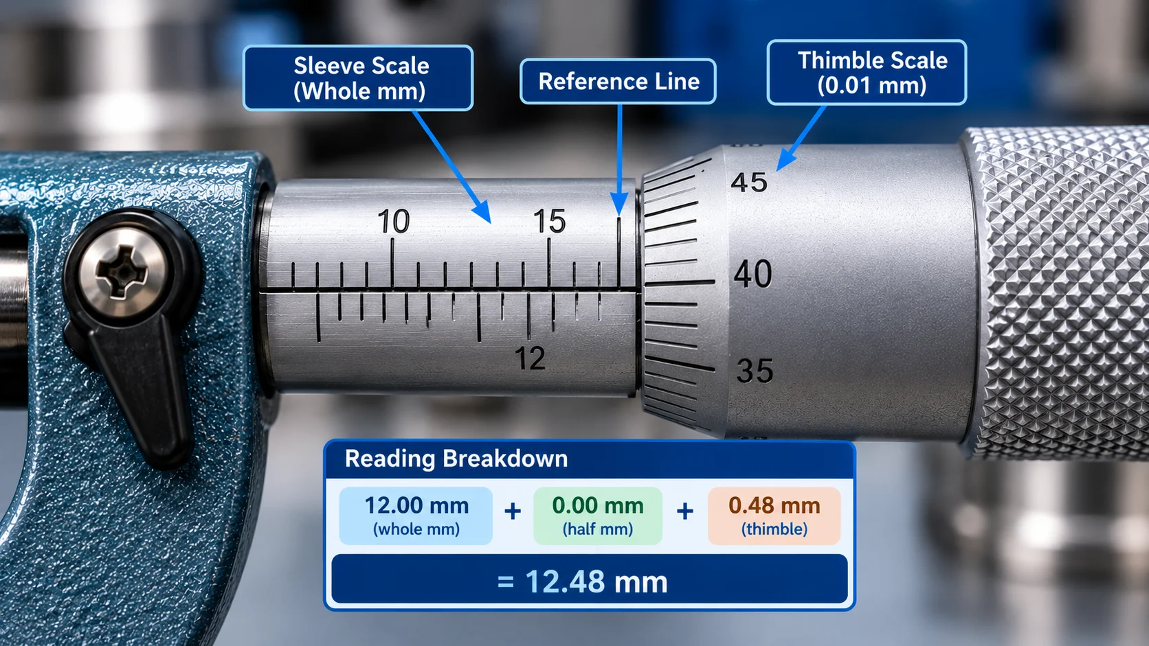
| 3 | 12.00 | 0.00 | 0.48 | 12.48 mm |
| 4 | 15.00 | 0.50 | 0.08 | 15.58 mm |
Example: Reading 12.48 mm
Suppose the last visible whole-millimeter mark is 12.00 mm, the next half-millimeter mark is not visible, and thimble division 48 aligns with the reference line.
Why Do Beginners Miss the Half-Millimeter Mark?
On many metric micrometers, the half-millimeter graduations are positioned on the opposite side of the reference line from the whole-millimeter marks.
Inspect both sets of graduations before adding the thimble contribution.
How to Read an Inch Micrometer Step by Step
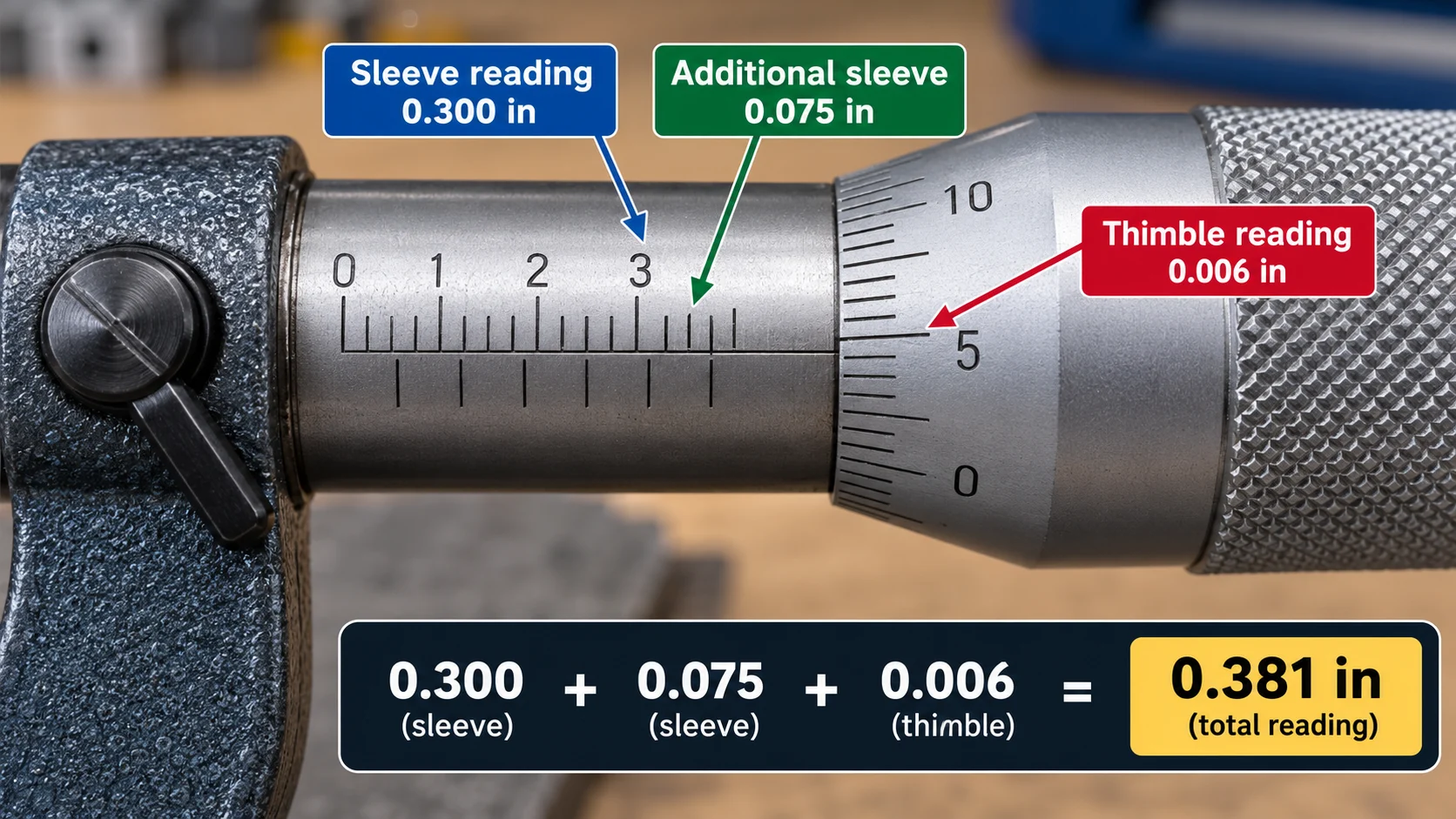
A conventional inch micrometer commonly uses a spindle with 40 threads per inch. One complete thimble revolution therefore advances the spindle by 0.025 inch.
With 25 thimble divisions, each graduation represents 0.001 inch.
Read the Main Sleeve Value
Find the main numbered sleeve graduation. In this example, the sleeve shows 0.300 inch.
Count Additional Sleeve Divisions
Three additional divisions at 0.025 inch each contribute 0.075 inch.
Read the Thimble
Thimble division 6 aligns with the reference line, adding 0.006 inch.
Calculate the Measurement
Add the sleeve and thimble values using inches throughout.
Metric vs Inch Micrometer Reading
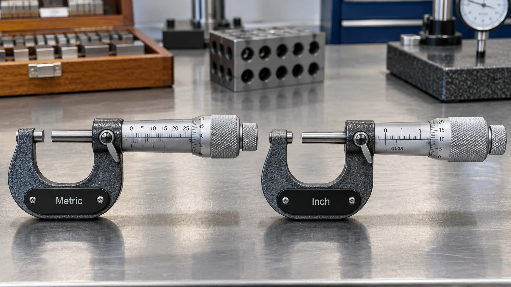
Metric and inch micrometers can look nearly identical, but their graduations represent different units.
| Feature | Metric | Inch |
|---|---|---|
| Measurement Unit | Millimeters | Inches |
| Common Sleeve Increment | 0.50 mm | 0.025 in |
| Common Thimble Increment | 0.01 mm | 0.001 in |
| Common Vernier Increment | 0.001 mm | 0.0001 in |
| Typical Use | Metric dimensions | Inch dimensions |
Can You Convert Micrometer Readings?
Yes. After obtaining the measurement in its original units, use the exact relationship between inches and millimeters.
How to Read a Vernier Micrometer
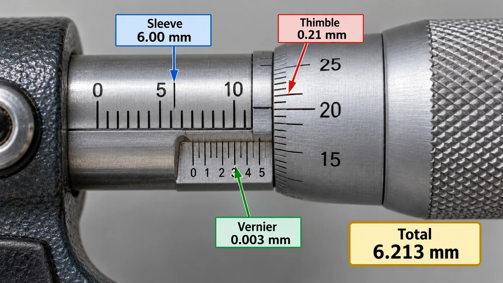
A vernier micrometer has an additional graduated scale for finer readings than the conventional sleeve-and-thimble combination.
Some metric vernier instruments allow readings in increments of 0.001 mm.
Steps to Read a Vernier Micrometer
- Read the main sleeve value.
- Read the thimble graduation.
- Identify the aligned vernier graduation.
- Add the three contributions.
| Scale | Example Value |
|---|---|
| Main Sleeve | 6.00 mm |
| Thimble | 0.21 mm |
| Vernier | 0.003 mm |
| Total | 6.213 mm |
Does Finer Resolution Mean Greater Accuracy?
Not necessarily. Finer graduations allow a smaller indicated increment, but actual accuracy depends on calibration, instrument condition, measurement force, temperature, and technique.
How to Use a Micrometer Correctly
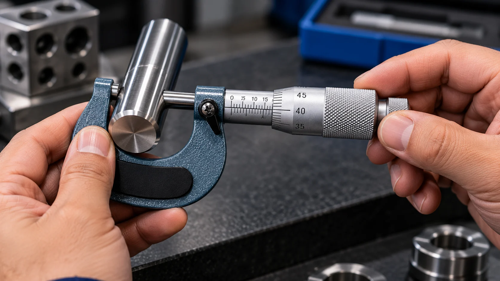
Interpreting the scale correctly is only one part of precision measurement. The instrument must also be handled properly.
Clean the Measuring Faces
Remove dirt, metal chips, and other contamination using an appropriate cleaning method.
Check the Instrument
Inspect the measuring faces, spindle movement, and zero or reference condition.
Position the Workpiece
Place the component between the anvil and spindle. Align the measuring faces with the dimension being measured.
Apply Consistent Measuring Force
Use the ratchet or friction device according to the manufacturer’s instructions. Avoid excessive force.
Read and Record the Result
Interpret the scales and record the measurement with the correct units.
Repeat When Necessary
Measure at suitable locations when checking wear, taper, or dimensional variation.
Interactive Measuring Checklist
Micrometer Least Count, Resolution and Accuracy
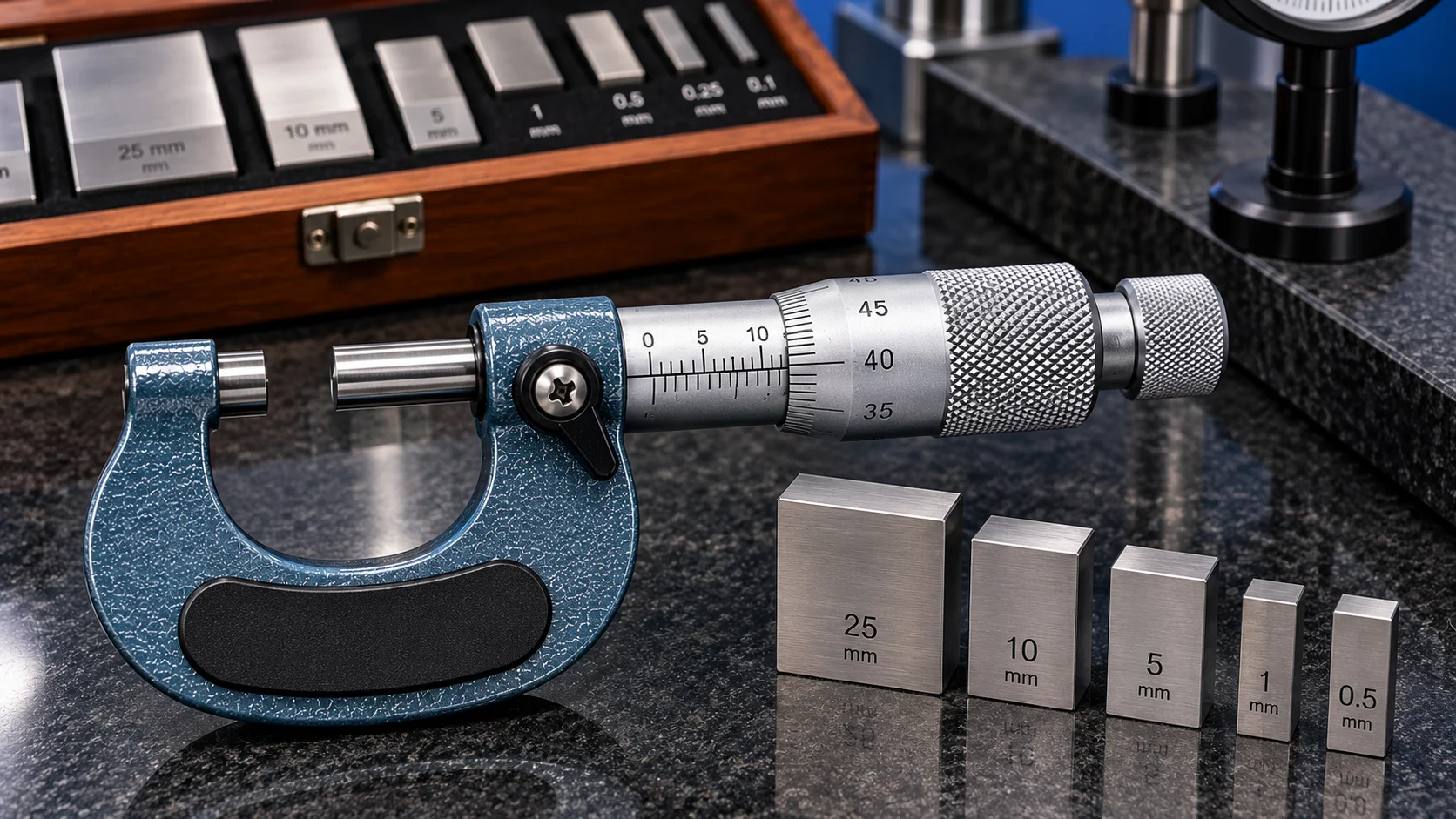
Resolution describes the smallest indicated measurement increment an instrument can display or distinguish.
In introductory measurement lessons, this is sometimes called the least count.
Micrometer Scale Increment Formula
Metric Example
A conventional metric micrometer with 0.50 mm spindle travel and 50 thimble divisions has:
Inch Example
An inch micrometer with 0.025-inch travel per revolution and 25 divisions has:
Resolution vs Accuracy
| Term | Meaning |
|---|---|
| Resolution | Smallest indicated increment. |
| Accuracy | Closeness of a result to a reference value. |
| Repeatability | Consistency under repeated comparable measurements. |
| Calibration | Comparison against suitable reference standards. |
| Measurement Uncertainty | Quantified doubt associated with a measurement result. |
How to Check Micrometer Zero Error
Before taking a precision measurement, check that the instrument indicates the expected reference value.
For a typical 0–25 mm outside micrometer, the measuring faces should indicate zero when properly cleaned and brought together using the specified force.
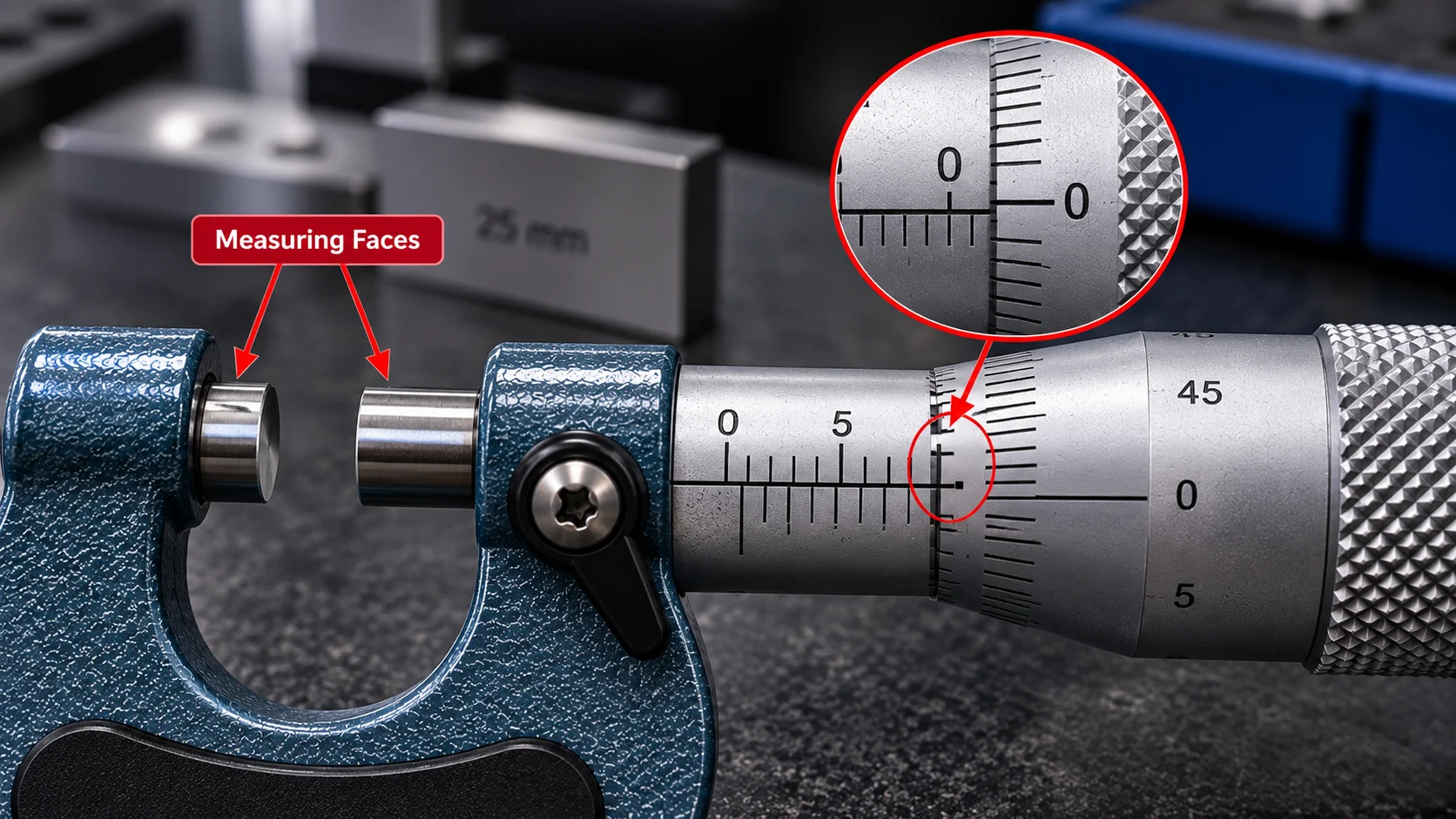
How to Check Zero Error
- Clean the measuring faces.
- Allow suitable temperature stabilization.
- Close the measuring faces using the specified force.
- Check the indicated reference value.
- Follow the manufacturer’s verification or adjustment procedure if necessary.
Zero Error Correction Example
Suppose a verified micrometer has a stable positive indication error of +0.02 mm. If the indicated measurement is 10.36 mm and this correction is valid, subtract the error.
What About Larger Micrometers?
Micrometers with measuring ranges that do not begin at zero may require appropriate setting standards instead of fully closed measuring faces.
Analog vs Digital Micrometers
Mechanical micrometers use graduated sleeve and thimble scales, while digital models provide an electronic numerical display.
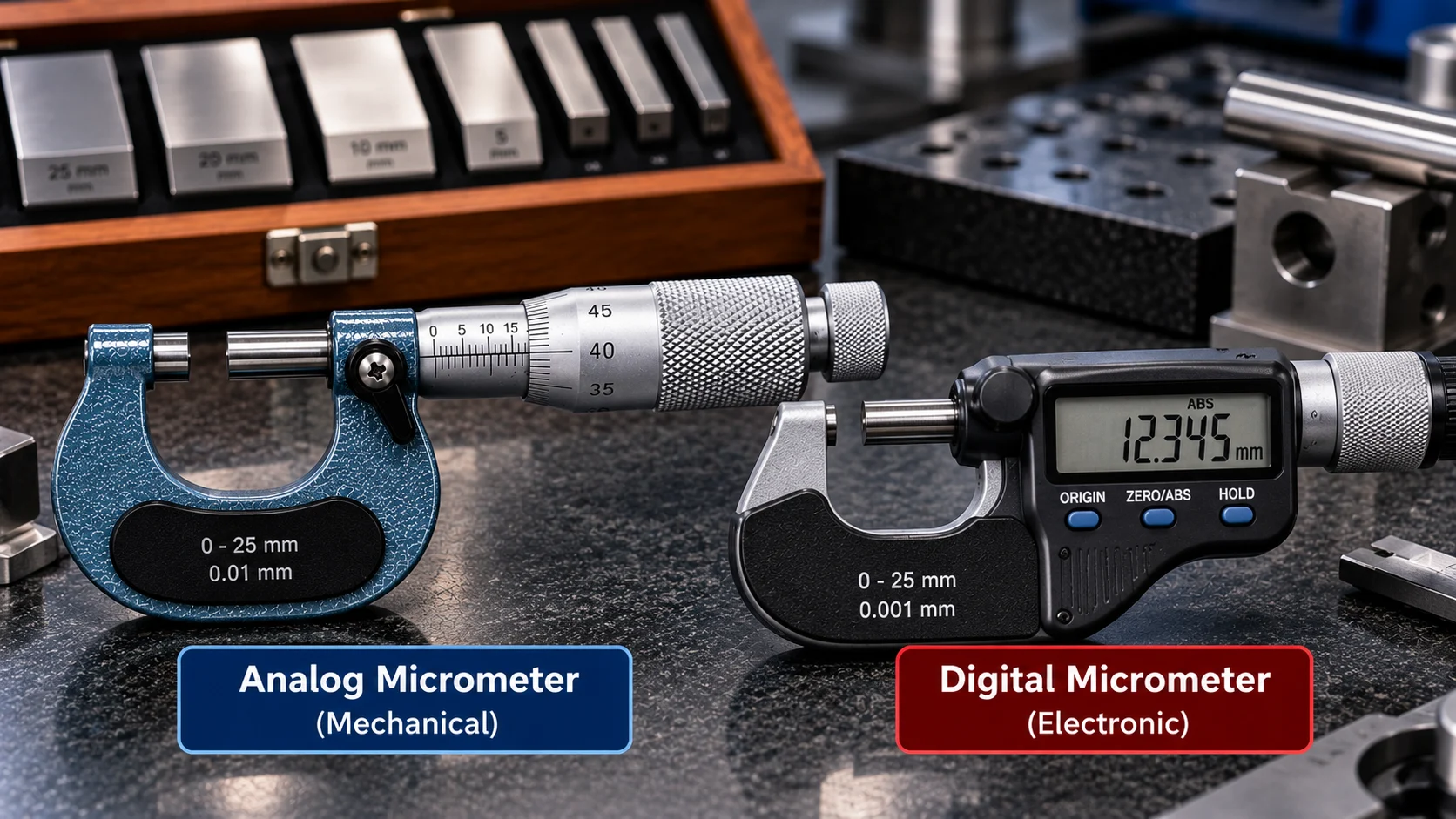
| Feature | Analog | Digital |
|---|---|---|
| Reading | Manual interpretation | Electronic display |
| Battery | Usually unnecessary | Usually required |
| Unit Switching | Depends on model | Available on some models |
| Resolution | Graduation dependent | Display and model dependent |
| Accuracy | Specification dependent | Specification dependent |
| Care | Mechanical care | Mechanical and electronic care |
Are Digital Micrometers More Accurate?
Not automatically. Digital displays can make results easier to read, but the instrument’s accuracy depends on its specifications, calibration, condition, and measuring technique.
Micrometer vs Vernier Caliper: Which Should You Use?
Micrometers and vernier calipers are both valuable measuring tools, but their strengths differ.
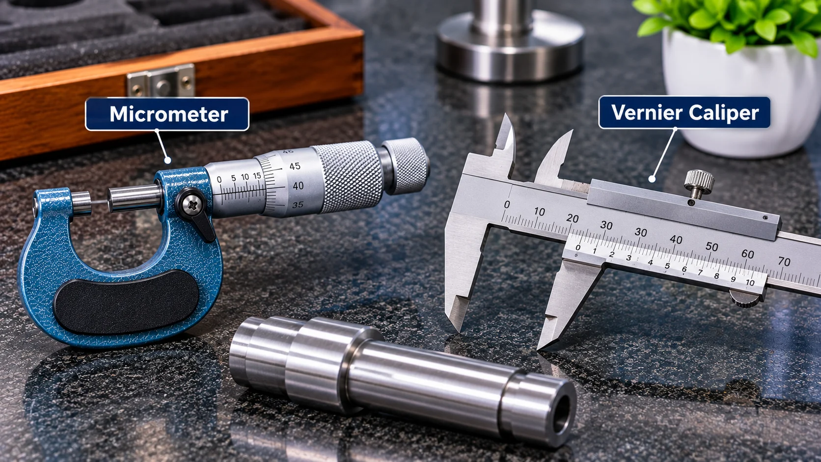
| Feature | Micrometer | Vernier Caliper |
|---|---|---|
| Primary Strength | Precision measurement of suitable features | Versatile dimensional measurement |
| Range | Often limited per instrument | Often broader per instrument |
| Outside Measurement | Yes | Yes |
| Inside Measurement | Specialized models | Common caliper feature |
| Depth Measurement | Depth micrometer | Common caliper feature |
| Example | Critical shaft diameter | General component sizing |
When Should You Use a Micrometer?
A suitable micrometer may be preferable for inspecting a specific feature with controlled measuring force and measurement performance appropriate to the required tolerance.
Choose the instrument based on measurement uncertainty, workpiece geometry, and inspection requirements.
Common Micrometer Reading Mistakes and How to Avoid Them
Measurement errors can result from incorrect scale reading, poor alignment, excessive force, surface contamination, or instrument condition.
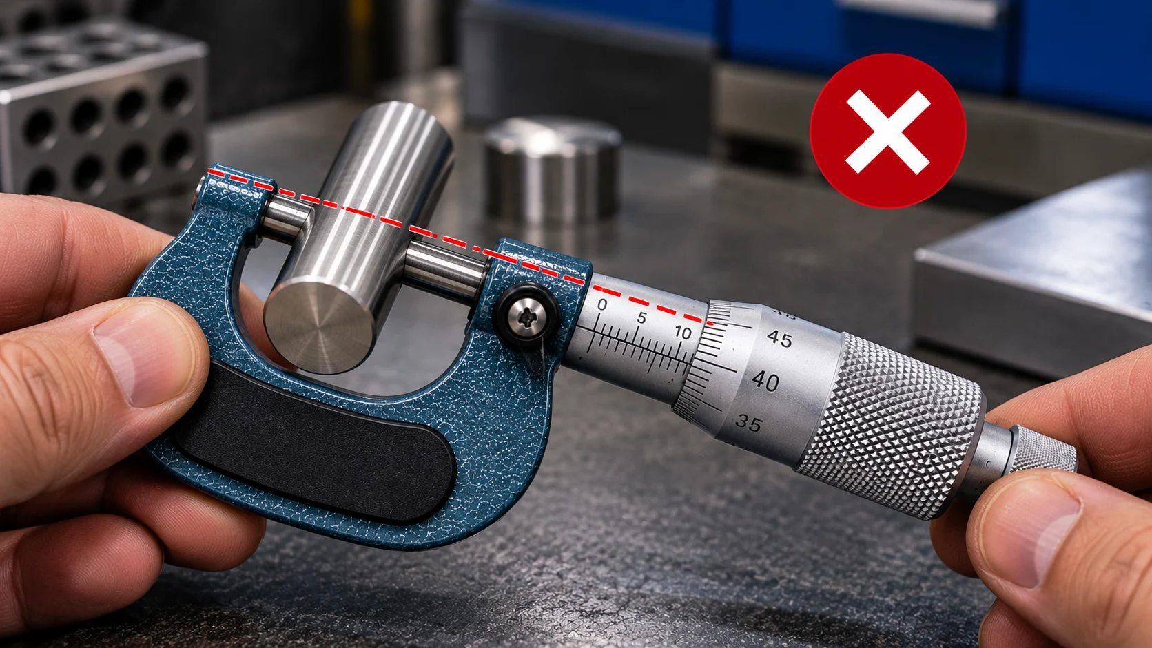
| Mistake | Possible Result | Correct Practice |
|---|---|---|
| Ignoring 0.5 mm Mark | Metric reading error | Check half-millimeter scale |
| Wrong Thimble Division | Incorrect fine reading | Check reference line |
| Confusing Units | Incorrect interpretation | Verify units first |
| Excessive Force | Measurement distortion | Use force-control mechanism |
| Poor Alignment | Dimensional error | Align measuring faces |
| Dirty Faces | Measurement offset | Clean faces |
| Temperature Differences | Dimensional variation | Use suitable conditions |
| Unverified Reference | Systematic error | Check zero or standard |
How to Improve Measurement Repeatability
- Use a consistent measuring force.
- Keep measuring faces clean.
- Maintain correct workpiece alignment.
- Use the appropriate micrometer range.
- Repeat measurements when necessary.
- Allow suitable temperature stabilization.
- Verify the instrument’s reference condition.
Micrometer Applications in Automotive and Machining Work
Small dimensional differences can affect mechanical component fit, wear, and serviceability. Micrometers help technicians check these dimensions against specified limits.

| Application | Purpose |
|---|---|
| Crankshaft Journal | Inspect diameter and dimensional variation. |
| Brake Rotor | Check thickness at specified positions. |
| Machined Shaft | Verify outside diameter. |
| Metal Sheet | Inspect material thickness. |
| Precision Spacer | Check thickness against a specification. |
| Manufactured Component | Verify dimensional compliance. |
Example: Inspecting a Crankshaft Journal
An engine technician may measure a crankshaft journal at multiple positions and orientations to check for diameter variation, taper, or wear.
The measurements must be compared with the actual engine manufacturer’s service specifications.
How to Maintain and Store a Micrometer
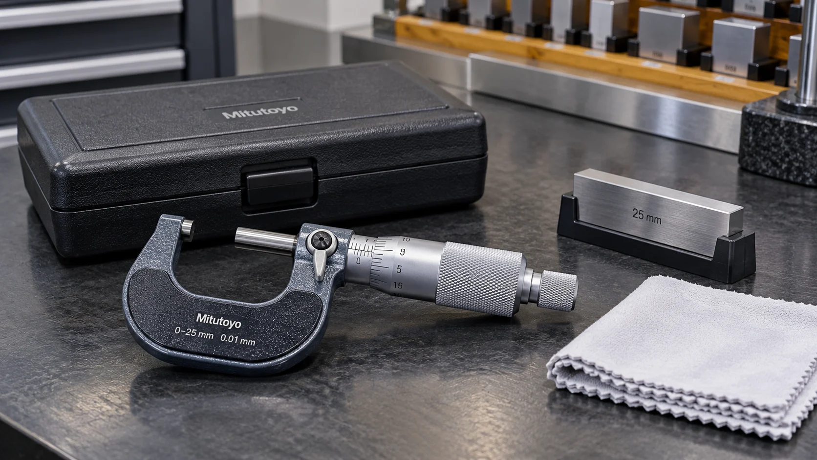
A micrometer is a precision instrument that requires careful handling, cleaning, and appropriate storage.
Micrometer Maintenance Checklist
- Clean the measuring faces appropriately after use.
- Protect the instrument from impact or dropping.
- Avoid excessive moisture.
- Store in a suitable protective case.
- Use manufacturer-approved corrosion prevention when appropriate.
- Do not force the spindle.
- Check reference readings periodically.
- Follow the required calibration procedure.
Should You Store a Micrometer Fully Closed?
Follow your instrument manufacturer’s storage instructions. Many mechanical micrometers are stored with a small gap between the measuring faces, but recommendations vary.
Micrometer Reading Practice Exercises
Now test your knowledge of metric, inch, and vernier readings. These exercises use the conventional scale systems explained above.
How to Improve Micrometer Reading Skills
Practice identifying the sleeve, thimble, half-millimeter, and optional vernier contributions. Then verify your technique with suitable measurement standards under controlled conditions.
Frequently Asked Questions About Micrometer Reading
How do you read a micrometer for beginners?
Read the main sleeve graduation, identify the thimble division aligned with the reference line, and add the values. Include the half-millimeter or vernier contribution when applicable.
What is the formula for micrometer reading?
For a conventional mechanical micrometer, the reading equals the sleeve contribution plus the thimble contribution. Add the vernier contribution if equipped.
How do you read a 0.01 mm micrometer?
Read whole millimeters and any visible half-millimeter graduation on the sleeve. Add the aligned thimble division multiplied by 0.01 mm.
How do you read an inch micrometer?
On a conventional inch micrometer, count the 0.025-inch sleeve increments and add the thimble value in 0.001-inch increments.
What does the half-millimeter mark mean?
It adds 0.50 mm when visible beyond the last whole-millimeter mark on a conventional metric micrometer.
What is the least count of a micrometer?
A standard metric mechanical micrometer often has 0.01 mm scale increments, while a conventional inch micrometer often has 0.001-inch increments. Other models differ.
How do you read a vernier micrometer?
Read the sleeve and thimble, then add the contribution of the aligned vernier graduation according to the instrument’s scale.
How do you check micrometer zero error?
Follow the manufacturer’s reference-check procedure. For a common 0–25 mm outside micrometer, the cleaned measuring faces should indicate zero when correctly closed with the specified force.
Are digital micrometers more accurate?
Not automatically. Accuracy depends on the model’s specifications, calibration, condition, and measurement technique.
Why do micrometer readings change?
Differences may result from temperature, measuring force, alignment, surface contamination, instrument condition, or actual workpiece variation.
What is the difference between a micrometer and a vernier caliper?
A micrometer is commonly used for precision measurement of suitable features. A general-purpose caliper provides greater versatility for outside, inside, and depth measurements.
Can you measure brake rotor thickness with a micrometer?
Yes. A suitable brake micrometer can measure rotor thickness at specified inspection locations. Compare the measurements against the vehicle manufacturer’s service specifications.
Final Thoughts: Mastering Micrometer Reading
Learning how to read a micrometer is a practical skill for automotive technicians, machinists, engineering students, and quality-control professionals.
The process becomes easier once you understand the main scale, fine scale, and measurement units.
For a conventional metric micrometer, combine the whole-millimeter, half-millimeter, and thimble values. For a conventional inch micrometer, combine the sleeve and thimble increments.
Vernier-equipped instruments provide an additional fine-scale reading. Always use the proper measuring technique and check the instrument’s condition before relying on a result.
Editorial note: This article provides general educational guidance. Follow the exact micrometer manufacturer’s instructions and applicable professional inspection procedures.