
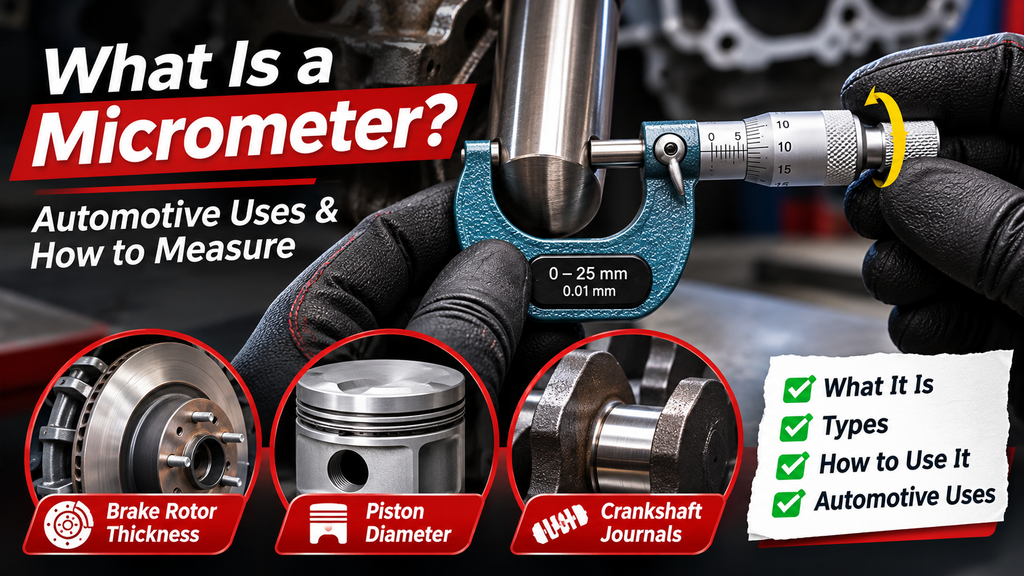
When a mechanic checks whether a brake rotor is too thin or an engine builder measures a crankshaft journal, an ordinary ruler is not precise enough. These jobs require a measuring instrument that can detect very small differences in dimensions. That instrument is often a micrometer.
A micrometer is a precision measuring tool used to measure dimensions such as thickness, diameter, and depth. In automotive repair, technicians commonly use micrometers to check brake discs, piston skirts, crankshaft journals, and other machined components.
Understanding how a micrometer works is useful for DIY mechanics and automotive students. However, there is an important difference between learning how to read a micrometer and performing engine measurements accurate enough to make machining or component-replacement decisions.
This guide explains the main parts, types, and measuring techniques, with practical automotive examples and clear guidance on which jobs are suitable for beginners and which require professional precision.
QUICK ANSWER: WHAT IS A MICROMETER?
A micrometer is a precision instrument that measures small dimensions using a calibrated measuring mechanism. An outside micrometer is commonly used to measure shaft diameters and component thicknesses. Automotive technicians use suitable micrometers to inspect brake rotor thickness, piston skirt diameter, crankshaft journals, and other parts against manufacturer specifications.
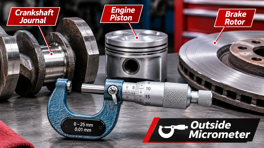
What Is a Micrometer Used for in Automotive Repair?
A micrometer helps determine whether a component’s measured dimension is consistent with the applicable manufacturer specification.
In an automotive workshop, this is particularly important when inspecting brake components, fitting engine parts, and evaluating machined surfaces.
| Automotive Component | Measurement | Suitable Instrument |
|---|---|---|
| Brake rotor | Disc thickness and thickness variation | Suitable brake disc micrometer |
| Engine piston | Piston skirt diameter | Outside micrometer |
| Crankshaft journal | Diameter, taper, and out-of-round | Precision outside micrometer |
| Camshaft journal | Outside diameter | Outside micrometer |
| Valve stem | Stem diameter | Suitable outside micrometer |
| Cylinder bore | Internal diameter and shape variation | Dial bore gauge or suitable inside measuring instrument |
These measurements serve different purposes. A brake rotor check helps determine whether a disc remains within service limits, while piston and crankshaft measurements are often part of more complex engine inspection and machining procedures.
Important: A number displayed by a micrometer is only useful when the instrument, measurement location, technique, and manufacturer specification are correct.
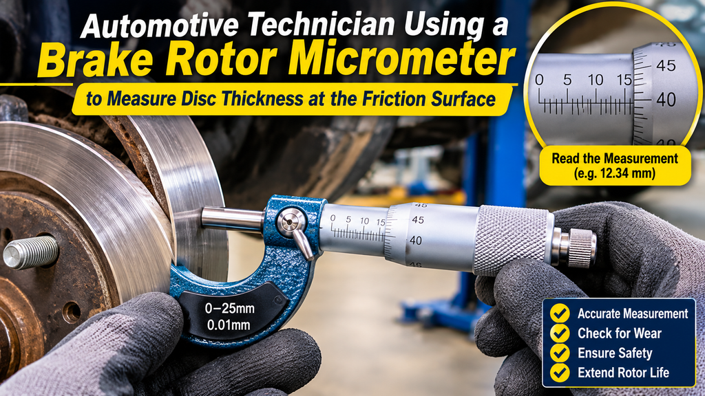
How to Measure Brake Rotor Thickness With a Micrometer
Brake rotors gradually wear as the brake pads contact their friction surfaces. Measuring rotor thickness helps determine whether a disc meets the vehicle manufacturer’s service requirements.
A suitable brake micrometer can provide more appropriate contact geometry than a general-purpose outside micrometer when the rotor has a raised outer wear lip.
Why Brake Rotor Thickness Matters
A rotor that has reached or fallen below its specified discard thickness must be replaced.
Thickness variation around the rotor can also be relevant when investigating brake judder or pulsation. However, symptoms alone cannot establish that the rotor is defective.
A technician may also need to inspect rotor runout, surface condition, installation, hub condition, and other braking components.
General Brake Rotor Thickness Inspection
- Identify the rotor specification. Find the correct minimum or discard thickness and inspection procedure for the vehicle.
- Prepare the vehicle safely. Follow the vehicle manufacturer’s wheel, brake, and support procedures. Never work under an improperly supported vehicle.
- Clean the measuring surfaces. Use the approved cleaning method and keep contamination away from the measuring contacts.
- Select the correct brake micrometer. Ensure its measuring faces reach the specified friction area and do not contact the outer wear ridge.
- Measure at multiple points. Follow the service manual’s required locations and number of measurements around the rotor.
- Record the readings. Identify the lowest thickness and any relevant variation.
- Compare with the correct specification. A rotor at or below its discard limit must be replaced, and other service restrictions may apply.
Some GM procedures specify at least four evenly spaced thickness measurements at a consistent distance from the rotor’s outer friction edge. Other manufacturers may require different positions or measurement counts.
Therefore, do not use a fixed number of measuring points or a universal thickness limit for every car.
Brake Safety: Do not assume a rotor is safe because its thickness appears acceptable at one point. Severe scoring, cracks, excessive thickness variation, and other defects require separate inspection. Brake disassembly and service should follow the vehicle manufacturer’s procedure.
Example: Understanding Brake Disc Thickness Variation
Suppose four measurements on a hypothetical rotor produce the following results:
| Measuring Position | Example Thickness |
|---|---|
| Position 1 | 24.02 mm |
| Position 2 | 24.00 mm |
| Position 3 | 23.98 mm |
| Position 4 | 24.01 mm |
The largest reading is 24.02 mm, and the smallest is 23.98 mm. The thickness difference is therefore 0.04 mm.
This example demonstrates the calculation only. It does not establish whether a particular rotor is safe or out of specification. That requires the correct service limits and measurement procedure.
How Mechanics Measure Piston Diameter With a Micrometer
Engine pistons operate inside cylinders with carefully specified clearances. A piston that does not have the correct dimensional relationship with its cylinder bore may create reliability, lubrication, noise, or wear problems.
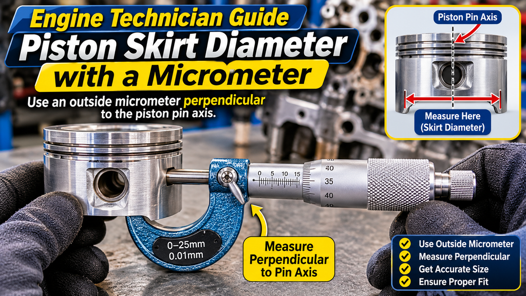
When inspecting a piston, an engine technician may use an outside micrometer to determine the piston skirt diameter at the correct location.
Where Should You Measure a Piston?
A piston is not necessarily a perfect cylinder. Its geometry may account for temperature changes and operating loads.
Therefore, measuring across the piston crown or an arbitrary point on the skirt can produce a dimension that is not appropriate for evaluating clearance.
The measurement is commonly taken across the skirt, perpendicular to the piston-pin axis, at a height specified by the engine or piston manufacturer.
The exact location varies by piston design. The technician should use the specified measuring point, not a guessed distance from the skirt edge.
Piston-to-Cylinder Clearance Explained
Piston-to-cylinder clearance describes the dimensional difference between the specified cylinder bore diameter and piston measuring diameter under defined conditions.
Basic Clearance Calculation
Cylinder Bore Diameter − Piston Diameter = Diametral Clearance
Example: 86.00 mm − 85.96 mm = 0.04 mm.
These are hypothetical dimensions used only to explain the calculation. They are not specifications for a particular engine.
A cylinder bore must be measured with suitable internal measuring equipment. The piston micrometer reading alone cannot establish the clearance.
Piston coatings, temperature, surface condition, and engine-specific measuring instructions can also affect the interpretation of results.
DIY vs. professional: A beginner can learn how a micrometer measures piston dimensions. Determining whether a piston and cylinder can be reused or machined requires appropriate tools, reliable reference measurements, and engine-specific specifications

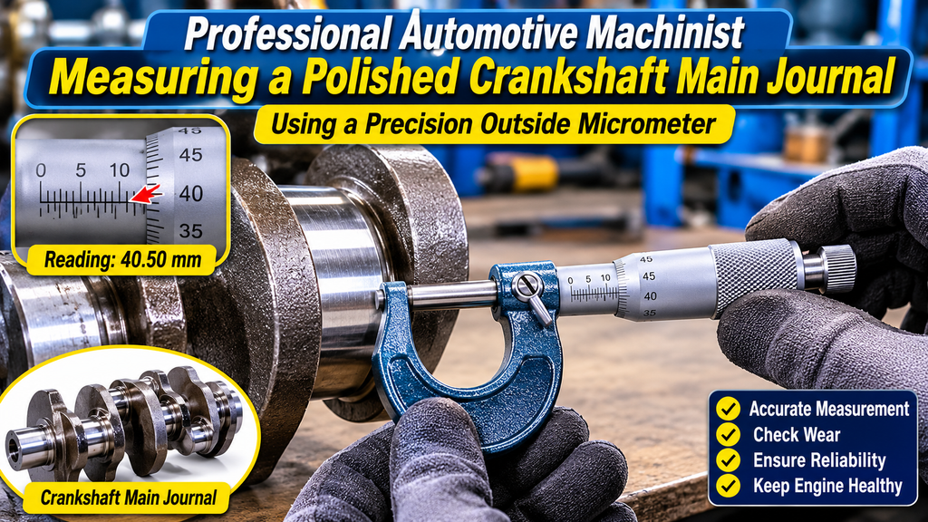
Measuring Crankshaft Journals With a Micrometer
A crankshaft contains precision-machined bearing surfaces known as journals. Main journals support the crankshaft in the engine block, while connecting-rod journals connect to the connecting rods.
During engine inspection or rebuilding, technicians measure these surfaces to assess diameter, taper, and out-of-round conditions.
An appropriately sized and verified outside micrometer can measure journal diameters. However, one reading does not provide a complete assessment of journal condition.
Journal Diameter, Taper, and Out-of-Round
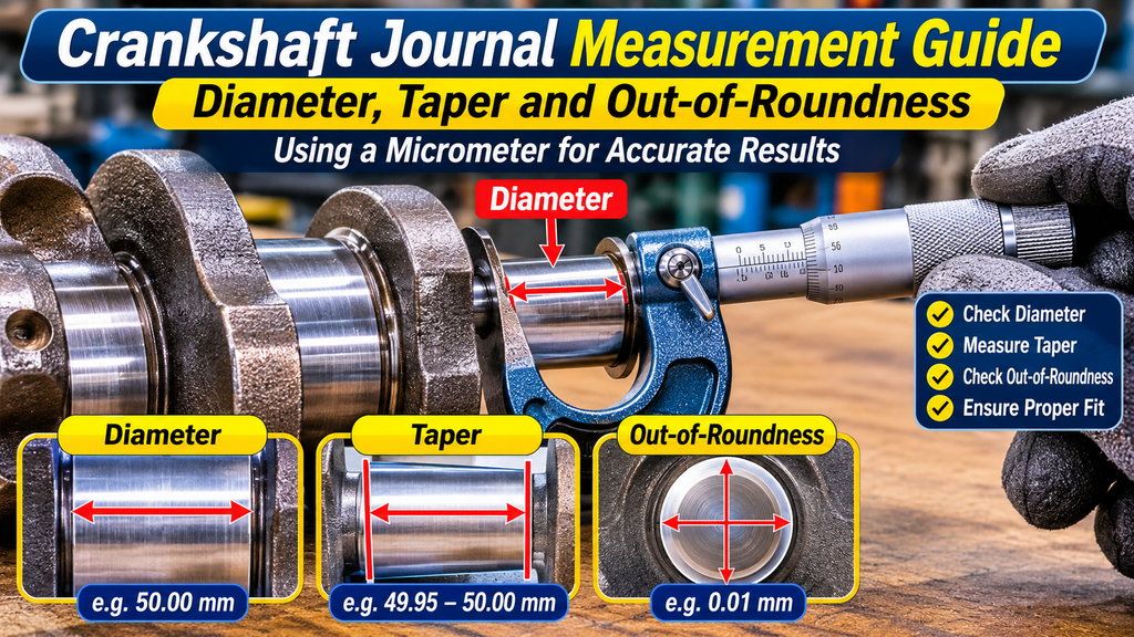
Three important measurements are commonly considered during crankshaft inspection.
| Measurement | What It Describes | How It Is Evaluated |
|---|---|---|
| Diameter | Size of the journal | Measured at specified positions with an outside micrometer |
| Taper | Difference in diameter along the journal’s width | Compare measurements at different axial positions |
| Out-of-Round | Variation in diameter around a cross-section | Compare readings in different orientations |
For example, if the diameters measured across a journal at two specified axial locations differ, that difference may contribute to its calculated taper.
If readings vary with orientation at the same axial location, this can indicate an out-of-round condition.
The technician must compare results with the correct engine specification before determining whether machining, bearing selection, or replacement is necessary.
Journal diameter measurement is also different from crankshaft runout measurement, which commonly uses a dial indicator and an appropriate support arrangement.
Engine Rebuild Warning: Do not use generic journal diameters, clearance limits, or machining tolerances to decide whether an engine part is reusable. Values differ by engine and component specification.
Parts of a Micrometer and Their Functions
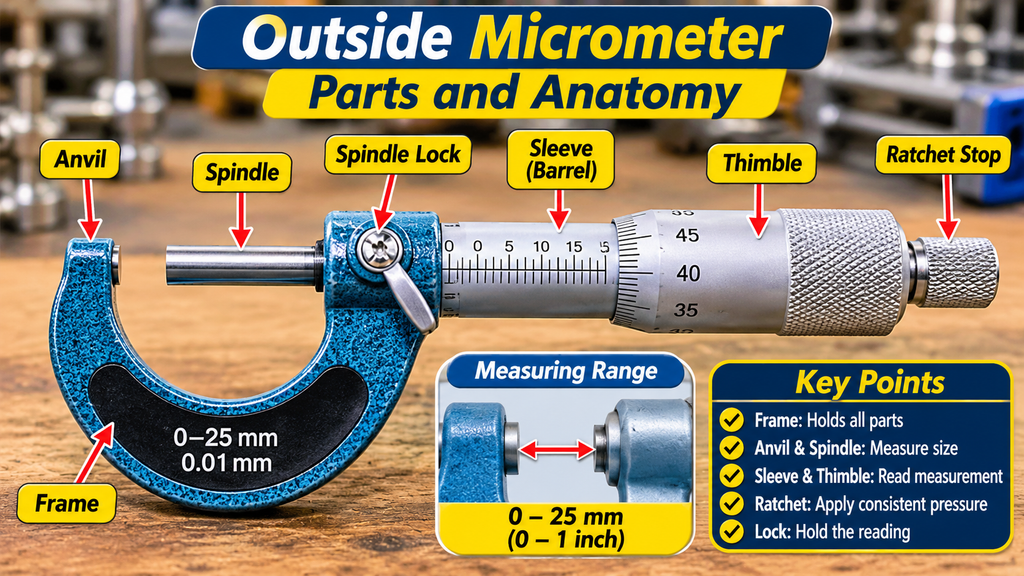
Most traditional outside micrometers share several important components. Understanding them helps beginners position the instrument and read it correctly.
| Part | Function |
|---|---|
| Frame | Provides structural support for the instrument. |
| Anvil | Fixed measuring contact. |
| Spindle | Movable contact that approaches the component. |
| Sleeve | Displays the main mechanical scale. |
| Thimble | Turns the measuring screw and displays fine scale divisions. |
| Ratchet or friction drive | Helps apply a controlled measuring force. |
| Spindle lock | Holds the spindle position when fitted. |
How Does a Micrometer Work?
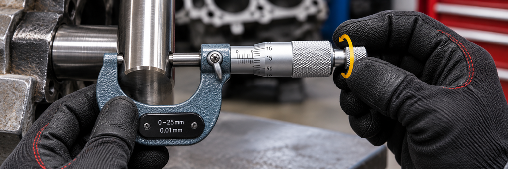
A traditional mechanical micrometer uses a precision screw mechanism. Turning the thimble moves the spindle toward or away from the fixed anvil.
When the measuring contacts correctly touch the component, the amount of spindle movement indicates the dimension being measured.
The measuring faces, screw mechanism, instrument calibration, and applied force all influence the reliability of the reading.
What Is Micrometer Resolution?
Resolution is the smallest change an instrument can display or indicate.
A common metric mechanical micrometer may have scale graduations of 0.01 mm. Other instruments may provide finer indicated increments.
Resolution is not the same as accuracy. A digital micrometer displaying 0.001 mm does not automatically measure every component accurately within 0.001 mm.
Actual measurement capability depends on the instrument’s stated performance, verification status, technique, and environmental conditions.
How to Use a Micrometer Correctly: Step by Step
The following is a basic procedure for learning how to use an outside micrometer on an accessible, suitable component.
Critical automotive inspections may require additional preparation and specific measurement methods.
- Choose the correct instrument. Confirm that the micrometer’s range and contact design match the dimension.
- Inspect the tool. Look for damaged measuring faces, worn parts, or signs of impact.
- Clean the contact surfaces. Remove contamination from the micrometer and the component using approved methods.
- Check the measuring reference. Follow the instrument’s zero or setting-standard procedure.
- Position the contacts correctly. Align the instrument with the specified dimension and measuring location.
- Apply consistent force. Use the instrument’s ratchet or friction drive as instructed.
- Read and record the result. Include the unit, component, and measuring location.
- Repeat where required. Additional readings may be necessary to establish variation or confirm repeatability.
Avoid using a micrometer as a clamp. Excessive force can affect the indication and may damage the instrument or workpiece.
How to Read a Micrometer in Millimeters and Inches
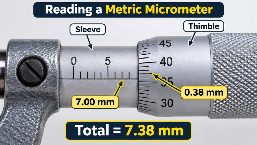
A mechanical micrometer usually combines graduations on the sleeve with smaller divisions on the rotating thimble.
The reading method depends on the specific scale design.
Reading a Standard Metric Micrometer
Consider a common metric micrometer with a 0.5 mm screw pitch and 50 thimble divisions. Each thimble division represents 0.01 mm.
Example Metric Reading
Whole millimeters: 7.00 mm
Additional half-millimeter mark: 0.00 mm
Thimble: 0.38 mm
Total: 7.38 mm
If the additional half-millimeter mark were exposed, the calculation would need to include that 0.50 mm.
Reading an Inch Micrometer
A common mechanical inch micrometer advances 0.025 inch per thimble revolution and uses 25 thimble divisions, giving 0.001 inch per division.
If the sleeve shows 0.200 inch and the thimble shows 0.007 inch, the result is 0.207 inch.
Some instruments include additional vernier graduations or different scale arrangements. Always follow the markings and user instructions for the instrument being used.
Types of Micrometers Used in Automotive Work
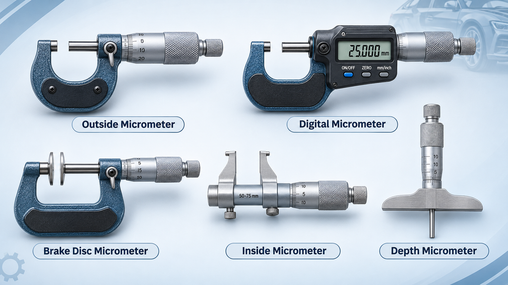
Different measuring tasks require different micrometer designs. A standard outside micrometer cannot directly measure every internal or specialized feature.
| Micrometer Type | Purpose | Automotive Example |
|---|---|---|
| Outside micrometer | Measures external dimensions | Crankshaft journal diameter |
| Brake rotor micrometer | Measures disc thickness with suitable contact geometry | Brake rotor thickness inspection |
| Inside micrometer | Measures suitable internal dimensions | Selected bores or internal features |
| Depth micrometer | Measures recesses and steps | Specified machining depth inspection |
| Digital micrometer | Displays measurements electronically | Precision measurement with suitable instrument geometry |
Micrometer vs. Caliper: Which Should Mechanics Use?
Both micrometers and calipers measure dimensions, but they are not interchangeable in every situation.
A caliper is versatile and useful for general workshop measurements. It can often measure external dimensions, internal dimensions, depth, and steps.
A micrometer is more specialized. It is typically designed for fine measurement over a smaller dimensional range.
| Feature | Micrometer | Caliper |
|---|---|---|
| Primary use | Fine dimensional measurement | General dimensional measurement |
| Typical individual tool range | Relatively narrow | Often broader |
| Measuring contact | Type-specific anvil and spindle | Jaws or depth feature |
| Measuring force | Often assisted by ratchet or friction mechanism | Generally controlled directly by user |
| Automotive example | Crankshaft journal inspection | General component dimensions |
Neither instrument is automatically accurate enough for every measurement. The required tolerance and instrument’s verified capability determine suitability.
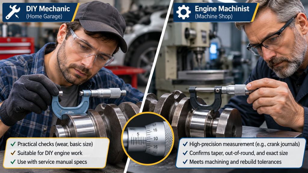
DIY Micrometer Use vs. Professional Machinist Precision
Understanding this distinction is essential for automotive readers.
A beginner can learn micrometer operation and perform educational measurements. However, making decisions about engine clearances or brake-component serviceability requires the right equipment, procedures, and qualifications.
| Task | Beginner / DIY | Professional Precision Needed? |
|---|---|---|
| Identify micrometer components | Suitable for learning | No |
| Practice reading sleeve and thimble | Suitable for learning | No |
| Measure a noncritical metal sample | Suitable with basic instruction | Not generally |
| Determine brake rotor serviceability | Requires correct service procedure and knowledge | Professional evaluation recommended |
| Select piston-to-cylinder clearance | Not a beginner measurement decision | Yes |
| Evaluate crankshaft taper and out-of-round | Advanced engine inspection | Yes |
| Determine machining or bearing sizes | Requires engine-specific measurements and standards | Yes |
A precision engine measurement may require calibrated micrometers, bore gauges, reference standards, stable temperature conditions, and manufacturer-specific specifications.
A DIY reading can be useful for learning, but it should not be treated as proof that a critical component is safe or ready for reuse.
Common Micrometer Measurement Mistakes
Errors can arise even when a micrometer appears to be working normally.
- Dirty contacts: Dust, metal particles, and other contamination can change the indicated dimension.
- Incorrect measuring force: Excessive pressure can affect measurements or damage components.
- Wrong measuring position: Measuring a piston or journal at an arbitrary location may not provide the required dimension.
- Incorrect alignment: Tilted contact faces may produce misleading readings.
- Skipped reference check: An instrument may have an unnoticed indication error.
- Confusing resolution with accuracy: Fine display increments do not establish measurement uncertainty.
- Temperature differences: Instrument and component expansion can matter during precision inspection.
- Using generic tolerance values: Acceptable dimensions must come from the correct vehicle or component specification.
How to Maintain and Check a Micrometer
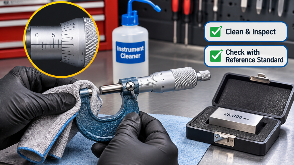
Store the instrument in a suitable protective case and keep its measuring faces clean. Follow the manufacturer’s instructions for corrosion prevention, lubrication, handling, and storage.
Check the instrument against the appropriate reference before using it for an important measurement.
A basic zero check is not the same as a complete calibration. Calibration requires an appropriate procedure and reference standards.
If a micrometer has been dropped or visibly damaged, do not assume it remains suitable for critical measurements.
How to Choose a Micrometer for Automotive Work
Before purchasing a micrometer, identify the component you need to measure and the precision required by its inspection procedure.
- Choose the measurement type. Use an outside micrometer for suitable external dimensions, a brake disc micrometer for applicable rotor checks, or another instrument for internal dimensions.
- Confirm the measuring range. The instrument must cover the expected dimension without exceeding its stated capacity.
- Check accuracy specifications. Display resolution alone does not establish suitability.
- Consider contact geometry. The anvil and spindle must reach the correct measuring surface.
- Review reference and calibration requirements. Precision engine inspection may require verified standards and professional measurement procedures.
- Choose mechanical or digital reading. Either can work when the instrument meets the required measurement specification.
For a beginner learning general outside measurements, a basic micrometer with appropriate reference documentation may be sufficient.
For engine rebuilding or machining, choose instruments according to the dimensions, tolerances, and measurement procedures specified for the work.
Frequently Asked Questions About Automotive Micrometers
1. What is a micrometer used for in cars?
Mechanics use micrometers to measure precision component dimensions, including brake rotor thickness, piston skirt diameter, and crankshaft journal diameter. The correct type and measurement procedure depend on the component.
2. Can you measure brake rotor thickness with a micrometer?
Yes. A suitable brake rotor micrometer can measure disc thickness at the locations specified by the vehicle manufacturer. The readings must be compared with the correct service specifications.
3. What micrometer is used for crankshaft journals?
A precision outside micrometer with the appropriate measuring range is commonly used. Technicians take measurements at multiple specified locations and orientations to evaluate diameter, taper, and out-of-round.
4. Where do you measure piston diameter?
Piston diameter is commonly measured at the skirt, perpendicular to the piston-pin axis, at a location specified by the piston or engine manufacturer. The correct measuring height varies by design.
5. Is a micrometer more accurate than a caliper?
A suitable micrometer is often preferred for fine dimensional inspection, but accuracy depends on the instrument and measurement conditions. Neither tool is automatically accurate enough for every application.
6. Can a beginner use a micrometer?
Yes. Beginners can learn the parts, practice reading graduations, and measure suitable noncritical samples. Precision engine and brake inspection requires additional knowledge, tools, and manufacturer specifications.
7. What is the difference between a digital and mechanical micrometer?
A digital micrometer displays the result electronically. A mechanical micrometer commonly uses sleeve and thimble graduations. Both require proper setup, measuring technique, and reference verification.
8. Can a micrometer measure the inside of an engine cylinder?
A conventional outside micrometer cannot directly measure a cylinder bore. Engine technicians commonly use a suitable bore gauge or other internal measuring instrument.
9. How accurate is a micrometer?
Accuracy depends on the instrument’s specifications, condition, calibration, measurement force, alignment, and environment. A fine display increment does not automatically guarantee equivalent accuracy.
10. Why is micrometer calibration important?
Calibration helps establish measurement performance against appropriate standards. This matters when a technician must decide whether a component meets a narrow dimensional tolerance.
11. Is a micrometer the same as the unit micrometer?
No. A micrometer measuring instrument is a tool. The micrometer unit, written as µm, equals one-millionth of a meter.
12. Who invented the micrometer?
Precision screw-measuring instruments developed over time. Jean-Laurent Palmer patented an important handheld micrometer caliper design in France in 1848, contributing to the development of the modern instrument.
Final Thoughts: Why Micrometers Matter in Automotive Repair
A micrometer is more than a tool for displaying small measurements. Used correctly, it helps technicians assess whether components meet precise dimensional requirements.
For automotive maintenance, a brake micrometer can help evaluate rotor thickness. During engine rebuilding, outside micrometers are used to inspect piston skirt diameters and crankshaft journals.
Beginners can learn the principles of micrometer measurement, but engine machining and critical brake inspections require suitable equipment, correct procedures, and reliable reference standards.
Key Takeaway: The most important part of using a micrometer is not simply reading a number. It is choosing the correct instrument, measuring at the right location, applying consistent technique, and comparing the result with the proper manufacturer specification.