
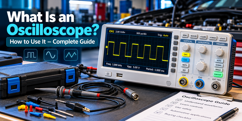
A vehicle can hesitate, misfire, or stall even when a quick voltage check looks normal. The missing clue may be the shape and timing of an electrical signal. That’s where oscilloscopes become valuable.
Quick answer: An oscilloscope is an electronic measurement instrument that displays how an electrical signal, usually voltage, changes over time. Instead of showing only a numerical reading, it displays a waveform that helps technicians investigate electrical pulses, timing, noise, missing signals, and intermittent faults.
This guide explains how oscilloscopes work, what their controls do, how to interpret waveforms, how to operate one safely, and how automotive technicians use them for vehicle diagnostics. You’ll also learn about different oscilloscope types, common mistakes, and buying considerations.
What Is an Oscilloscope?
An oscilloscope is a diagnostic instrument used to visualize electrical signals. Its display helps users observe voltage changes, waveform patterns, frequency, timing, and signal behavior.
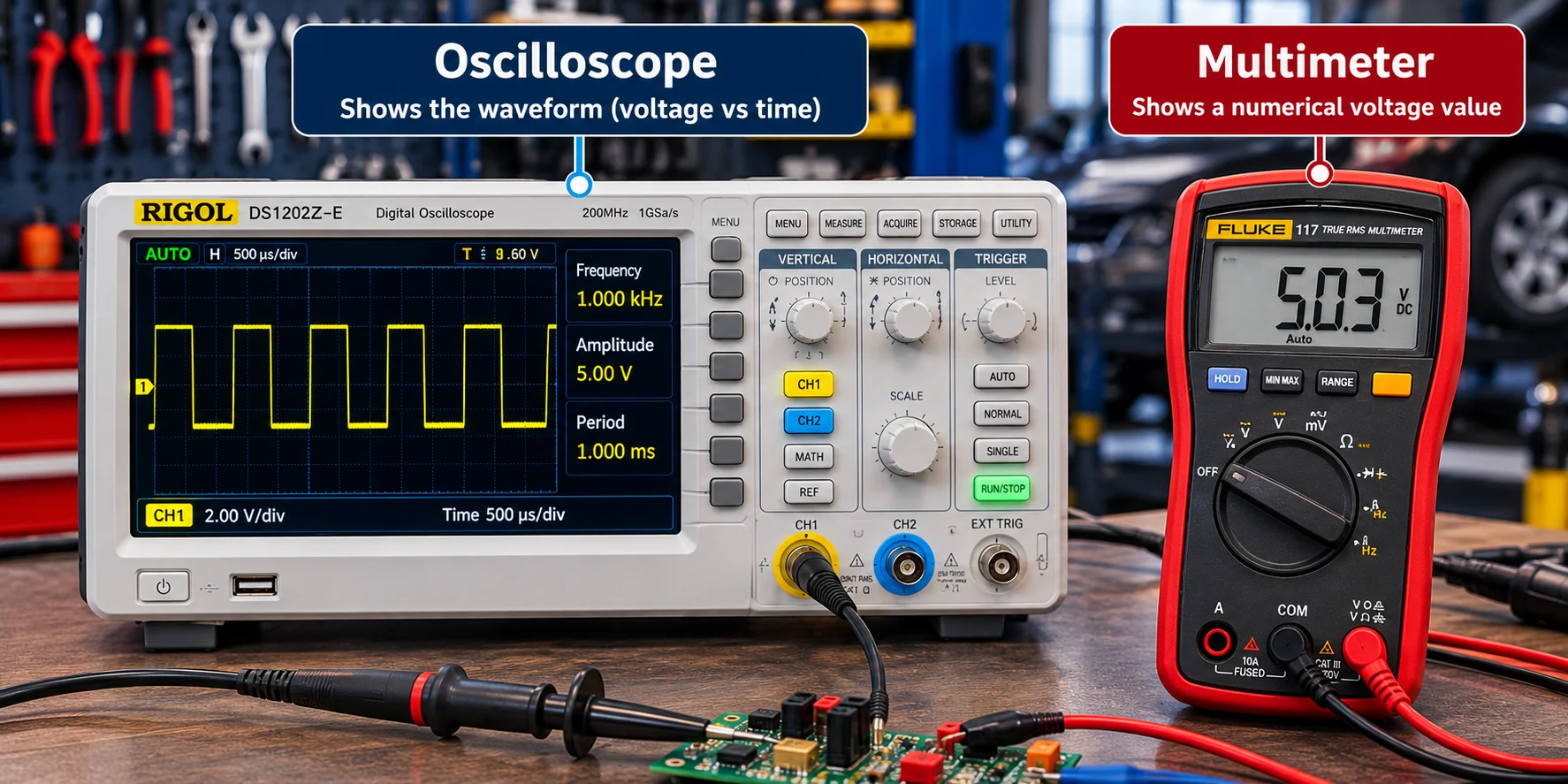
Think of a multimeter as a tool that reports a measurement, while an oscilloscope shows how a signal changes over time. A multimeter is excellent for many basic electrical checks, but an oscilloscope reveals changing waveforms.
What Are Oscilloscopes Used For?
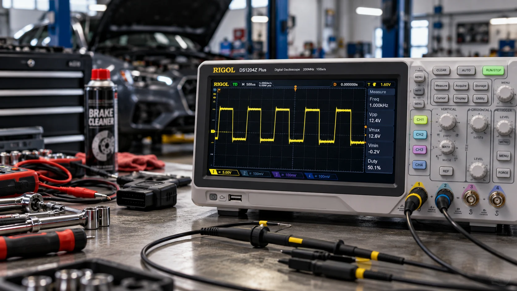
Oscilloscopes are used in electronics, automotive diagnostics, engineering, industrial maintenance, education, and product development.
Electrical Signal Analysis
Examine how voltage changes over time and identify unexpected fluctuations.
Automotive Diagnostics
Observe sensor outputs, control signals, injector commands, and electrical timing.
Electronic Circuit Testing
Analyze circuit behavior and compare expected signals with measured results.
Intermittent Fault Detection
Capture missing pulses, glitches, and other short electrical events.
Why Is an Oscilloscope Important?
Some electrical problems are difficult to understand from a single numerical reading. A crankshaft position sensor, for example, may produce an apparently reasonable reading while occasionally losing a pulse.
With the correct setup, an oscilloscope can help visualize that missing pulse and provide useful diagnostic information.
How Does an Oscilloscope Work?
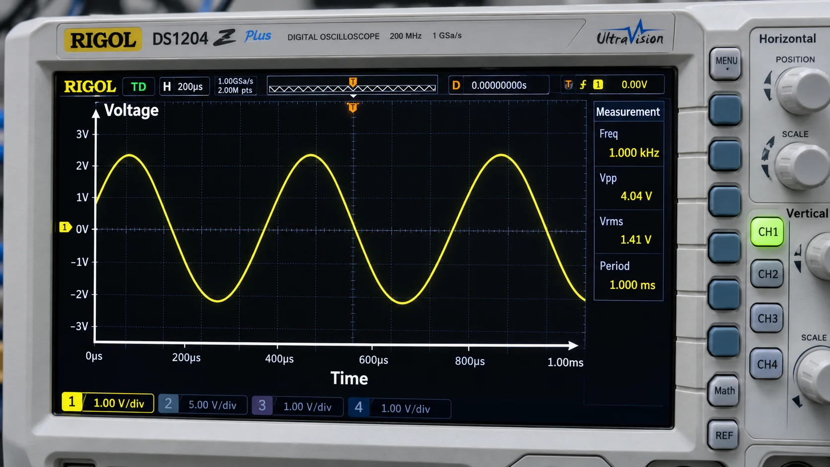
A digital oscilloscope receives an electrical signal through a suitable probe, processes the signal, and creates a waveform showing voltage against time.
The vertical axis typically represents voltage, while the horizontal axis represents time. This makes it possible to observe both the magnitude and timing of electrical activity.
Basic Working Process
Signal Input
A compatible probe connects the instrument to the electrical signal being measured.
Signal Processing
The input circuitry conditions the signal. A digital oscilloscope converts the voltage into samples for processing and display.
Waveform Display
The oscilloscope plots the measured signal so you can observe its shape, amplitude, and timing.
Measurement and Analysis
Technicians use cursors and measurement functions to evaluate voltage, frequency, period, and other waveform characteristics.
Analog vs Digital Operation
Traditional analog oscilloscopes use an analog display system to represent changing signals. Modern digital oscilloscopes sample electrical signals and use electronic processing to store and display waveforms.
Digital models generally provide useful capabilities such as waveform storage, automatic measurements, advanced triggering, and computer connectivity.
Main Parts and Controls of an Oscilloscope
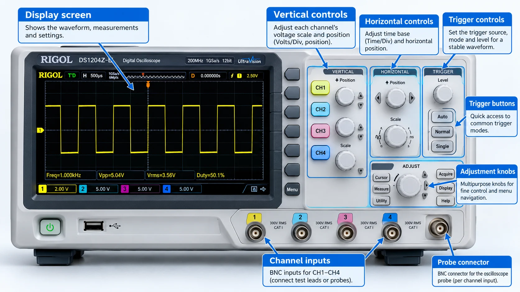
Learning the main oscilloscope controls is essential for accurate and useful measurements.
| Component | Function |
|---|---|
| Display Screen | Shows waveforms, measurements, channel information, and settings. |
| Channel Inputs | Allow one or more electrical signals to be connected through appropriate probes. |
| Vertical Controls | Adjust the displayed voltage scale and waveform position. |
| Horizontal Controls | Adjust the time scale and horizontal position of the waveform. |
| Trigger Controls | Determine when the oscilloscope captures or aligns the waveform. |
| Measurement Menu | Displays measurements such as frequency, period, and voltage. |
| Probe Connector | Connects compatible measurement probes to the instrument. |
What Does Volts/Div Mean?
Volts per division determines how much voltage each vertical grid division represents.
For example, at 2 V/div, a waveform spanning three vertical divisions represents a 6-volt difference, assuming the probe scaling is correctly configured.
What Does Time/Div Mean?
Time per division controls the horizontal time scale. At 1 ms/div, each horizontal division represents one millisecond.
What Is the Trigger Function?
Triggering allows the oscilloscope to start or align an acquisition when a specified signal condition is met.
For example, an edge trigger can stabilize the display by triggering when a signal crosses a chosen voltage level in a specified direction.
Understanding Oscilloscope Waveforms
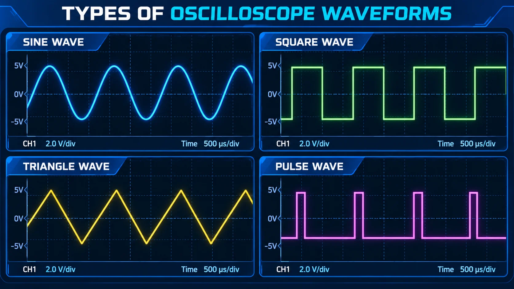
A waveform represents changes in an electrical signal over time. Different waveform shapes can reveal valuable information about the signal source.
Sine Wave
A smooth periodic waveform commonly associated with alternating electrical signals and some sensor outputs.
Square Wave
Alternates between two levels with relatively sharp transitions. Common in digital electronics.
Triangle Wave
Changes approximately linearly between maximum and minimum levels, creating a triangular pattern.
Pulse Wave
Contains active and inactive intervals. Pulse width and timing can reveal information about control signals.
Important Waveform Measurements
| Measurement | Meaning |
|---|---|
| Amplitude | The magnitude of a signal relative to its specified reference. |
| Peak-to-Peak Voltage | The difference between the highest and lowest voltage levels. |
| Frequency | The number of complete waveform cycles per second, measured in hertz. |
| Period | The time required for one complete waveform cycle. |
| Duty Cycle | The percentage of one period that a pulse signal remains active. |
| Rise Time | The time required for a signal to transition between specified low and high reference levels. |
What Does an Abnormal Waveform Mean?
Unexpected spikes, missing pulses, irregular timing, or excessive noise can indicate a possible electrical problem. However, an unusual waveform does not automatically prove that a component is faulty.
Always compare your measurement with the expected signal characteristics, relevant service information, and known-good examples.
Types of Oscilloscopes
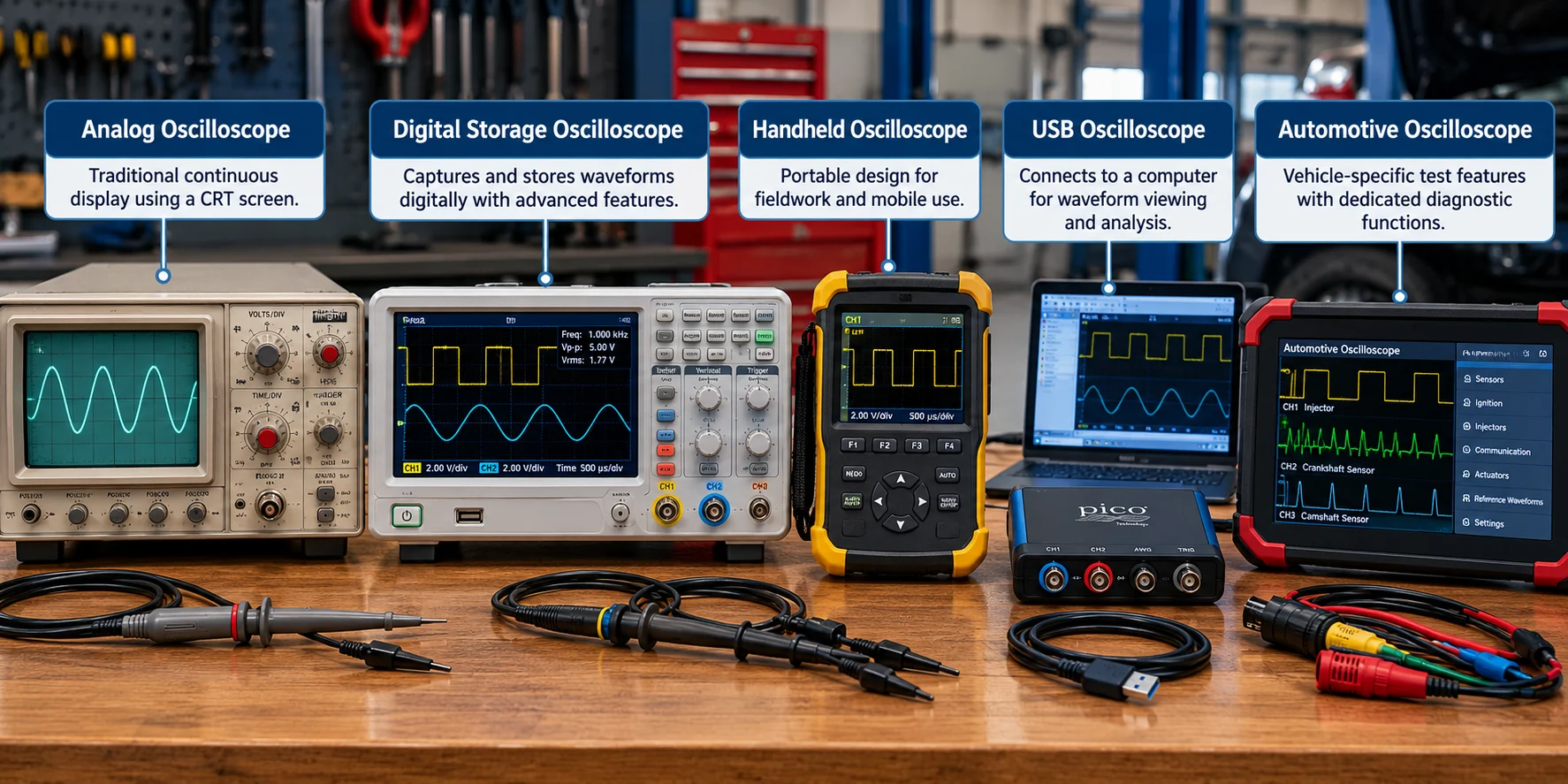
Different oscilloscopes are designed for different measurement tasks, operating environments, and budgets.
1. Analog Oscilloscopes
Analog oscilloscopes represent changing signals through an analog display system. They are less common in modern diagnostic applications but remain useful for understanding traditional measurement systems.
2. Digital Storage Oscilloscopes
Digital storage oscilloscopes, often called DSOs, capture signals digitally and can store waveforms for further analysis.
They are widely used in engineering, electronics repair, education, and automotive diagnostics.
3. Handheld Oscilloscopes
Handheld oscilloscopes combine portability with measurement functions, making them useful for fieldwork and workshops.
Some models include isolated inputs, but isolation and measurement ratings vary significantly between instruments.
4. USB Oscilloscopes
USB oscilloscopes connect to a computer for waveform viewing, analysis, and storage. Some automotive diagnostic systems use this approach.
5. Automotive Oscilloscopes
Automotive-focused oscilloscopes may include dedicated sensor tests, diagnostic software, reference waveforms, and supported accessories for vehicle measurements.
| Type | Main Advantage | Best Suited For |
|---|---|---|
| Analog | Traditional continuous display | Basic electronics and education |
| Digital Storage | Capture and store waveforms | General electronics diagnostics |
| Handheld | Portable operation | Field service and mobile work |
| USB | Computer-based interface | PC-based diagnostics |
| Automotive | Vehicle-specific test features | Automotive workshops |
Oscilloscope Probes and Safe Connections
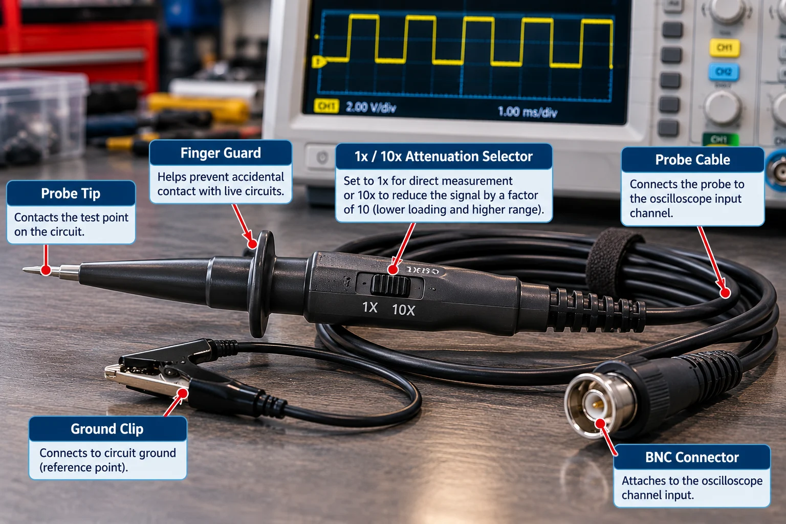
Oscilloscope probes connect an instrument to the electrical point being measured. Selecting the correct probe is essential for accurate results and safe operation.
1x vs 10x Oscilloscope Probes
A 1x probe transfers the signal without nominal 10-to-1 attenuation, while a properly compensated 10x probe reduces the voltage presented to the oscilloscope input by a factor of ten.
The oscilloscope channel setting must match the probe attenuation to display correct voltage measurements.
Understanding Probe Grounding
On many mains-powered benchtop oscilloscopes, the probe ground clip is electrically connected to protective earth through the instrument.
Probe Compensation
Passive probes may require compensation adjustment to reproduce waveforms correctly. Many oscilloscopes include a dedicated square-wave compensation terminal for this purpose.
Follow the probe and oscilloscope manufacturer instructions to perform the compensation check.
How to Use an Oscilloscope: Step-by-Step Guide
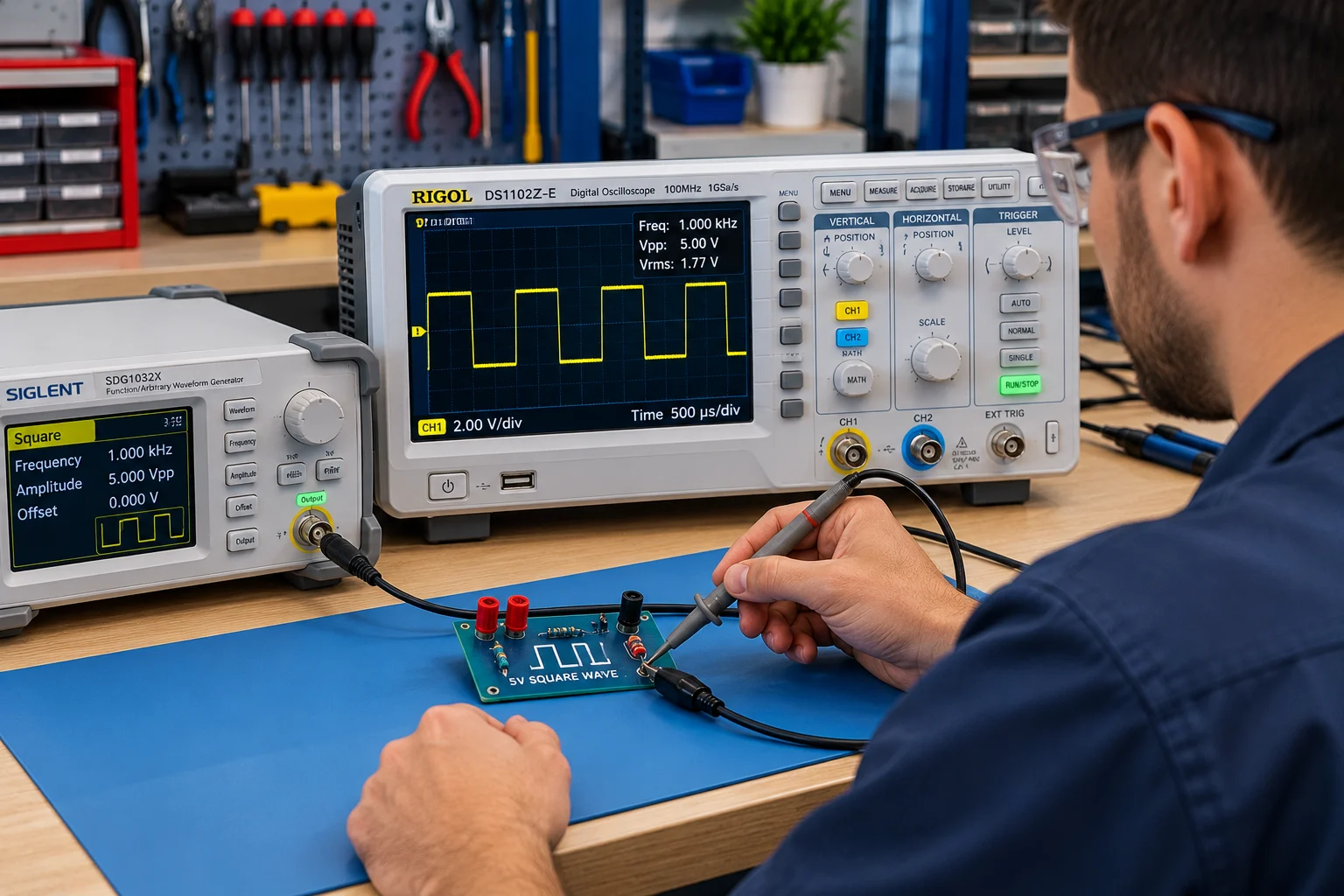
Learning to use an oscilloscope is easier when you begin with a known, low-voltage signal rather than a complicated automotive circuit.
Inspect the Equipment
Check the oscilloscope, probes, cables, and connectors for damage. Confirm that the instrument is appropriate for the measurement.
Power On the Oscilloscope
Start the instrument according to its manual. Select a suitable channel and initial settings.
Connect the Probe
Connect a compatible probe to the selected oscilloscope input. For a beginner exercise, use the built-in probe-compensation output as instructed in the manual.
Match the Probe Attenuation
Confirm that the oscilloscope’s 1x or 10x channel setting matches the actual probe configuration.
Adjust Volts/Div
Select a vertical scale that allows the waveform to fit comfortably on the display.
Adjust Time/Div
Select a horizontal time scale that shows enough signal cycles to understand the waveform.
Set the Trigger
Choose a suitable trigger source, edge direction, and threshold. Adjust the trigger level until the waveform becomes stable.
Measure and Save the Waveform
Use measurement functions or cursors to inspect the signal. Save a screenshot or waveform record if supported.
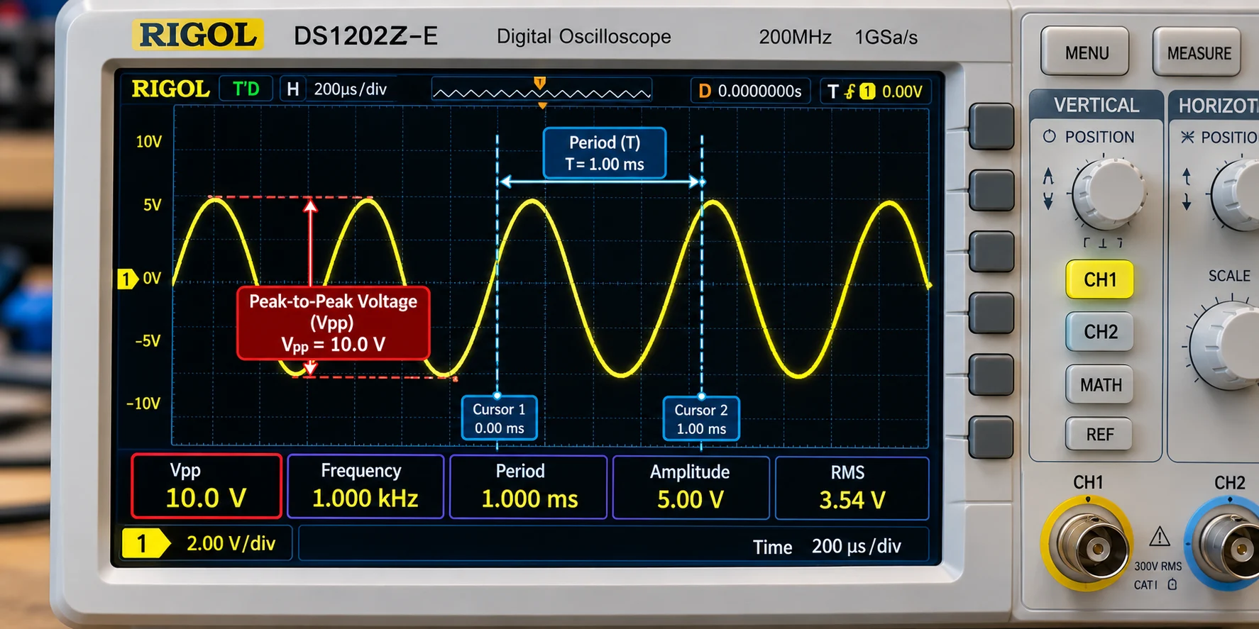
How to Read an Oscilloscope Screen
Reading a waveform becomes much easier once you understand how voltage and time are represented by the oscilloscope’s grid.
Measuring Peak-to-Peak Voltage
To calculate peak-to-peak voltage, count the vertical divisions between the waveform’s highest and lowest points and multiply by volts/div.
Measuring Frequency
Measure the time taken for one complete waveform cycle. The frequency is the reciprocal of the period measured in seconds.
Interactive Waveform Calculator
Use this calculator to estimate peak-to-peak voltage, waveform period, and frequency from oscilloscope grid measurements.
This calculator assumes a periodic waveform and correctly configured probe attenuation. It is a learning aid, not a substitute for instrument measurements.
How Oscilloscopes Are Used in Automotive Diagnostics
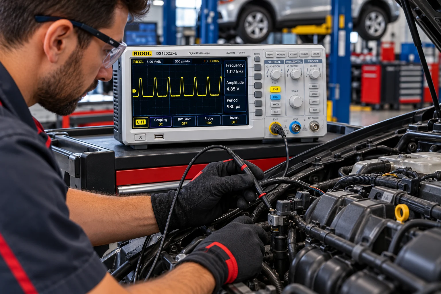
Automotive oscilloscopes help technicians analyze electrical signals from sensors, actuators, and vehicle control systems.
Unlike a basic voltage reading, a waveform can reveal signal timing, interruptions, pulse patterns, and transient behavior.
1. Crankshaft Position Sensor Testing
Crankshaft position sensors provide information about crankshaft position and engine speed. Depending on the sensor type, a technician may observe an alternating or digital waveform.
The expected pattern depends on the engine design and sensor system.
2. Camshaft Position Sensor Testing
Camshaft signals can be examined for proper operation and timing relationships with crankshaft signals.
3. Fuel Injector Control Signals
With appropriate measurement techniques, an oscilloscope can help examine injector command timing and related electrical behavior.
4. Ignition System Diagnostics
Suitable automotive probes and accessories can help technicians observe ignition-related signals. High-voltage ignition circuits require specialized equipment and safe diagnostic procedures.
5. Electrical Communication Signals
Oscilloscopes may help inspect electrical characteristics of vehicle communication networks when the technician understands the specific network and uses suitable connections.
| Component | Signal to Observe | Diagnostic Purpose |
|---|---|---|
| Crankshaft Sensor | Pulse pattern and timing | Check signal continuity and timing behavior |
| Camshaft Sensor | Position signal and timing | Compare signal behavior with specifications |
| Fuel Injector | Control pulses | Examine command duration and timing |
| Ignition Circuit | Suitable primary or secondary waveforms | Investigate ignition-related electrical behavior |
| Vehicle Network | Communication signal levels and patterns | Investigate physical-layer signal problems |
Oscilloscope vs Multimeter: What’s the Difference?
Oscilloscopes and multimeters are both valuable electrical diagnostic tools, but they answer different questions.
| Feature | Oscilloscope | Multimeter |
|---|---|---|
| Primary Output | Voltage waveform over time | Numerical electrical measurement |
| Changing Signals | Detailed waveform analysis | Limited by meter features and update rate |
| Frequency Measurement | Waveform and frequency analysis | Available on some models |
| Intermittent Problems | Can capture events with suitable triggering | May miss short events |
| Resistance Testing | Not typically a basic scope function | Standard function on most multimeters |
| Ease of Use | Requires waveform interpretation | Generally simpler for basic tests |
| Typical Cost | Often higher | Often lower |
Common Oscilloscope Mistakes and Troubleshooting
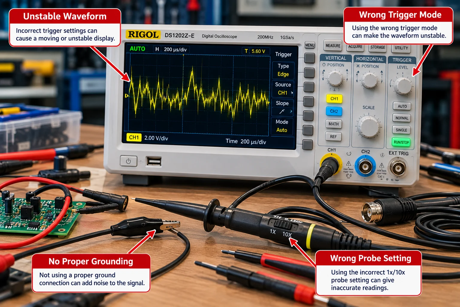
Many oscilloscope problems are caused by setup errors rather than faulty electrical components.
| Problem | Possible Cause | Solution |
|---|---|---|
| No Visible Waveform | Wrong channel or scale | Check channel, connections, and voltage scale |
| Unstable Waveform | Incorrect trigger settings | Adjust trigger source, mode, and level |
| Incorrect Voltage | Probe attenuation mismatch | Match probe and instrument settings |
| Distorted Signal | Probe compensation or bandwidth limitation | Inspect probe settings and instrument capabilities |
| Unusual Noise | Grounding, connections, or actual circuit noise | Use a safe, appropriate measurement setup |
| Misleading Signal Shape | Insufficient sampling or aliasing | Review sample rate and acquisition settings |
How to Improve Measurement Accuracy
- Choose the appropriate probe and attenuation setting.
- Confirm voltage and measurement ratings.
- Use a suitable time base and vertical scale.
- Configure triggering for the signal being tested.
- Check bandwidth and sample-rate limitations.
- Follow safe grounding and connection procedures.
- Compare measurements with reliable reference information.
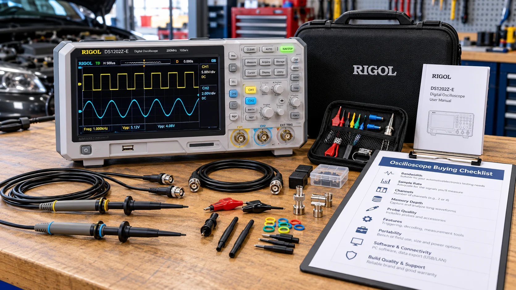
Oscilloscope Buying Guide and Checklist
The best oscilloscope depends on your intended applications, electrical measurement needs, experience level, and budget.
Important Features to Consider
Bandwidth
Choose enough bandwidth to capture the relevant frequency content and waveform details.
Sample Rate
The oscilloscope needs enough effective samples to represent the waveform accurately.
Number of Channels
Two channels are useful for beginners. Four or more can support complex automotive timing comparisons.
Memory Depth
Sufficient memory allows longer recordings while preserving useful detail.
Input Safety and Probes
Ensure the oscilloscope and accessories are properly rated for your intended measurements.
Software and Usability
Consider display quality, waveform storage, triggering, documentation, and software support.
Which Oscilloscope Is Best for You?
| User | Suggested Features |
|---|---|
| Electronics Beginner | Accessible two-channel DSO, clear controls, and suitable low-voltage probes. |
| DIY Automotive Enthusiast | Suitable automotive signal measurement capabilities, good triggering, and compatible accessories. |
| Professional Mechanic | Multiple channels, useful automotive software, reference waveforms, and supported probes. |
| Mobile Technician | Portable design, suitable input ratings, and practical field-use features. |
Interactive Buying Checklist
Frequently Asked Questions About Oscilloscopes
What are oscilloscopes used for?
Oscilloscopes display changing electrical signals and help analyze voltage, timing, frequency, pulse width, and waveform behavior. They are commonly used in electronics, automotive diagnostics, and engineering.
Is an oscilloscope difficult to learn?
Basic operation is approachable for beginners. Start with channel selection, probe connections, volts/div, time/div, and trigger controls. Advanced waveform interpretation takes additional knowledge and practice.
Can an oscilloscope measure DC voltage?
Yes. With the appropriate input configuration and DC coupling, a steady voltage normally appears as a horizontal trace at its measured level relative to the reference.
How many oscilloscope channels do I need?
Two channels are useful for beginner measurements and signal comparisons. Four or more channels can be beneficial for simultaneous automotive measurements.
Can an oscilloscope replace a multimeter?
Not completely. Multimeters are generally more convenient for routine voltage, resistance, and continuity measurements, while oscilloscopes are better suited to waveform and timing analysis.
What is the difference between volts/div and time/div?
Volts/div determines the vertical voltage scale, while time/div determines the horizontal time scale on the screen.
Why is my oscilloscope waveform unstable?
Common causes include incorrect trigger settings, inappropriate time scales, poor connections, or an irregular input signal.
Can I test car ignition systems with an oscilloscope?
Yes, with appropriate automotive probes, suitably rated equipment, and correct diagnostic procedures. High-voltage ignition measurements must not be made using ordinary unapproved probes.
What is a good oscilloscope for automotive beginners?
Look for clear controls, sufficient channel count, useful trigger functions, suitable measurement ratings, and compatible automotive accessories. Automotive-specific reference waveforms can also help with learning.
Final Thoughts: Are Oscilloscopes Worth Learning?
Oscilloscopes give you something a simple numerical measurement cannot: a detailed view of what an electrical signal does over time.
By learning how to adjust voltage and time scales, stabilize a waveform, interpret basic signal patterns, and use suitable probes, you can build valuable electrical troubleshooting skills.
For automotive diagnostics, oscilloscopes are particularly helpful when investigating sensor signals, timing relationships, intermittent faults, and electrical control behavior.
Editorial note: The examples in this guide are educational. Actual vehicle measurements and procedures vary between manufacturers and systems. Follow the oscilloscope manufacturer’s instructions and relevant vehicle service documentation.